TAGGED: acoustics, harmonic-analysis, porous-media
-
-
March 21, 2022 at 5:08 pm
kasparek1
SubscriberHello,
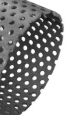
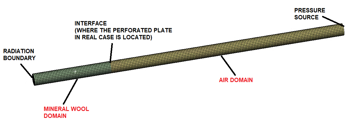
I am trying to perform analysis which evaluates how much energy is absorbed by acoustic panel in the circural tube (see pic 1). The acoustic panel consists of mineral wool glued to perforated plate. Holes in perforated plate lead to very difficult mesh, so I wanted to simplify it by removing the perforated plate from model and applying the Absorption Surface boundary condition to a surface where mineral wool and air domain meet. This BC should tell how much energy is ,,absorbed" (not really absorbed, because we know steel plate cannot absorb acoustic energy) by perforated plate itself. The problem is that even though I apply the Absorption Surface to the interface of both domains, SPL doesn't get lower when it goes through (see pic 2).
I just want to find a way how to avoid meshing holes in perforated plate and how to apply some BC to interface between mineral wool and air (where the perforated plate is located) instead (in this case the mesh wouldn't be so difficult but I am also making more difficult model where meshing of holes would lead to milions of elements). I also dont know if Absorption Surface is correct boundary condition to use in this case.
I would like to know what is the problem in my analysis and why isn't SPL lowering.
Any help will be appreciated.
Thanks in advance,
J
March 21, 2022 at 6:13 pmkasparek1
SubscriberHi Erik thanks a lot for your answer. I will try to search more about use of transfer admittance matrix.
I know about Delany Bazley model from your previous comments, so Ive already considered that, but thanks a lot anyway!
Have a nice day
J
March 21, 2022 at 7:09 pmErKo
Ansys EmployeeHi
Please see if you can use it (you need to know the transfer admittance) but do not use the square grid and the other grid option since that requires a curved pipe like those in a muffler so it is not really for perforated disc.
All the best
Erik
March 22, 2022 at 10:12 amkasparek1
SubscriberMarch 22, 2022 at 11:24 amErKo
Ansys EmployeeHi
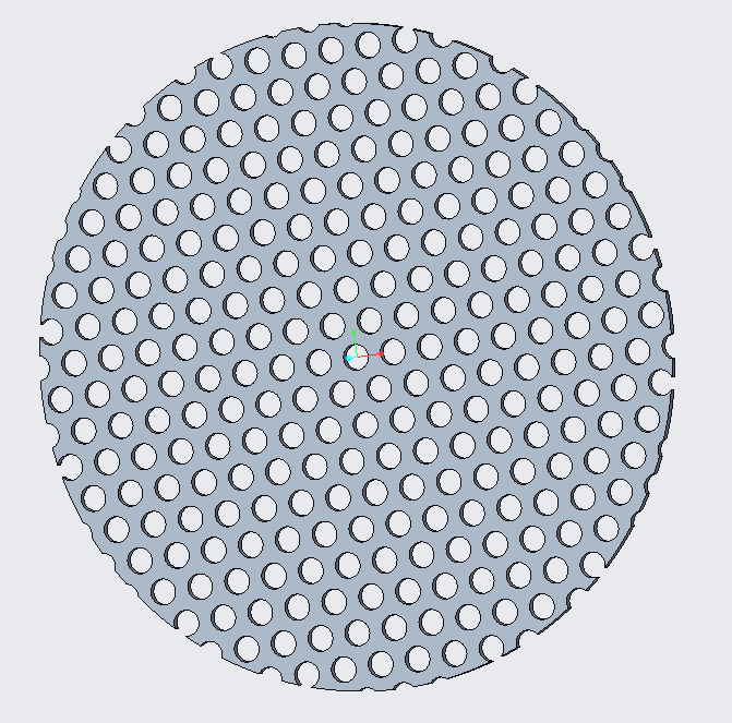
I think it could be possible to use that one (general admittance matrix YMAT), but how you can derive the terms I do not know (it is quite complex). As I mentioned the square grid option can not be used for your disc, it only applies to a curved perforated pipe (as shown in the image below), and you do not have that. Also really think why you need to model all this (what is the purpose of the analysis).

One can also use to certain extent the Delany-Bazley perforated material model for a rigid/steel perforated disc (you need to know the fluid resistivity though). Of course then we use this say for a complex set up say in a silencer, and before we can check the model say with the measured transmission loss of the perforated disc alone sitting in an impedance tube.
All the best
Erik
March 22, 2022 at 1:16 pmkasparek1
SubscriberOk thanks for the information.
I will try to explain my plans further to get it clear:
I have an experimental device: a hollow box - walls of the box are made of acoustic panels - non perforated steel sheet (1 mm thickness) - mineral wool (47 mm thickness) - perforated steel sheet (1 mm thickness). Perforated side is oriented to the inside of the box. Inside the box, there is omnisource (omnidirectional acoustic source). I am going to measure the difference between SPL inside the box and SPL outside the box (in all directions - X, Y, Z). The difference of these SPLs will be equal to Transmission Loss of each panel.
Now I want to model this whole situation in ansys, but there are three main problems:
1. I want to avoid meshing air domain inside the holes of perforated plate. That was the original question of this topic. But I dont know which boundary condition is ideal to use in this case.
2. Ansys will consider outside plate (non perforated) as fully reflective, but in real case it is not. How to model this?
3. How to model omnidirectional source?
I know its quite complex problem but I hope its clear what my goal is. If anyone knows how to answer any of questions, I will appreciate it.
Thanks in advance
K
March 22, 2022 at 2:44 pmErKo
Ansys EmployeeHi
Answers:
As you say, it will be difficult and perhaps impossible (depending how large the structure is) to model a large perforated structure, so use the Delany-Bazley (DB) perforated material model (defined in engineering data) for a rigid/steel perforated disc , and the mineral wool. So you need to measure or get from the manufacturer the fluid resistivity of the perforated plating and the mineral wool, and enter that in the engineering data for the DB material. This model (DB) works to a certain extent of course and it can not cover all applications, but is worth a try here. It does work OK and has been used for mineral wool, but not sure how accurate and what the limitations are for perforated plates.
You need to model the 1 mm steel plate (solid elastic - structural physics region in harmonic acoustics). So you will have a fully coupled vibro-acoustic analysis.
If you put a mass source excitation on a vertex at the centre, it will give you a spherical acoustic wave.
Finally once you are done with that, you can transfer the outside structural velocities of the 1 mm steel plate to an acoustic exterior domain surrounding the structure, and conduct the exterior acoustics (so calculate spl outside the box).
This is what we call a one way coupled acoustic analysis, that is when structural velocities are transferred to a pure acoustic model, then they are mapped on to the the acoustic mesh and we can calculate the sound generation due to these structural velocities.
All the best of luck
Erik
March 22, 2022 at 8:20 pmkasparek1
SubscriberHello Erik thank you again so much for all the help, I really appreciate it.
I get point 1 and point 3, I will try it for sure. I just have one additional question for point 2 since I have never done a coupled analysis. Does this mean that there will be ,,two analysis coupled in one"? If I understand it correctly - I set some pressure to omidirectional source as excitation and I evaluate velocities generated on non-perforated plate. In second analysis these velocities will be an excitation and I will be able to evaluate SPL in mics outside the box. Am I right?
Thank you and have a nice day
K.
March 23, 2022 at 8:01 amErKo
Ansys EmployeeHi
So for a vibroacoustic analysis (harmonic acoustic system) you will have both the 1 mm steel plate (structural physics region), and the 2 acoustic physics regions (DB foam and DB perforation sheet which will just be a 1mm thick homogeneous solid part so without the holes). See this thread to see the physics regions, and details.
For the 3rd point use one way coupling, you will basically transfer the above results to a new harmonic system that has the exterior air surrounding the box. One way coupling is done like shown in the video/link below, but instead of the harmonic response you will use the above harmonic acoustics system to transfer the results to a new system (harmonic system of the exterior air).
All the best
Erik
March 24, 2022 at 7:15 pmkasparek1
SubscriberVery well explained. I will definitely try to do this and will inform about results. Thank you so much.
Have a nice day
K.
Viewing 9 reply threads- The topic ‘Harmonic Acoustic – Absorption Surface’ is closed to new replies.
Innovation SpaceTrending discussionsTop Contributors-
4818
-
1587
-
1386
-
1242
-
1021
Top Rated Tags© 2026 Copyright ANSYS, Inc. All rights reserved.
Ansys does not support the usage of unauthorized Ansys software. Please visit www.ansys.com to obtain an official distribution.
-


