TAGGED: end-release
-
-
March 20, 2022 at 11:15 am
DIANAG
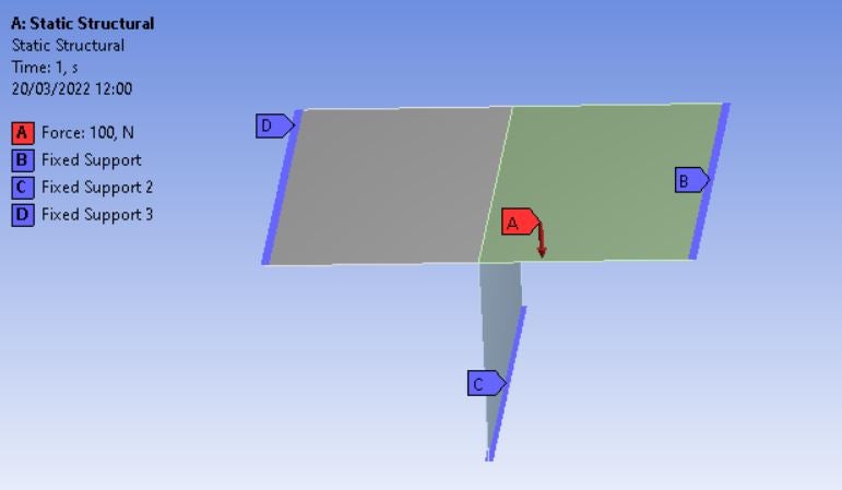
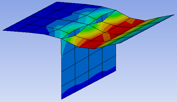
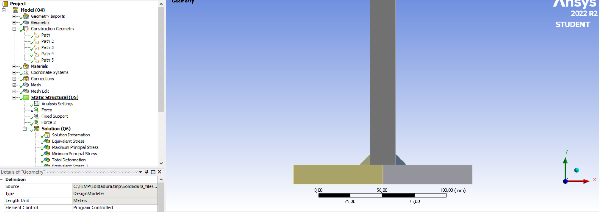
SubscriberHi everyone, I have a very simple problem to solve but I don't know how. I have this kind of structure, with two orthogonal plates, three fixed supports and a force applied only on one face as shown below.
March 20, 2022 at 12:56 pmpeteroznewman
SubscriberHello Diana I tried one way to do this, but it was very tedious so I only did 3 out of 5 nodes that would be a complete job for this coarse mesh. I sure hope someone can describe an easier method!
 In SpaceClaim, use two components to avoid accidentally using Shared Topology. You need the nodes along the center of the top plate to be separate from the nodes along the top of the vertical plate.
Use Mesh Controls to guarantee the same number of nodes along each edge. Mesh the plates. I used 5 nodes (4 elements) along each center edge.
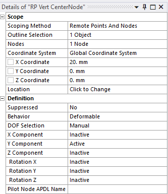
Hide the vertical plate and make 5 Remote Points, one for each node along the centerline. Invert visibility and make 5 Remote Points, one for each node along the top of the vertical plate. Name each Remote Point so you can pair up the nodes later. For example, I used Vert and Top in the name to know which plate the Remote Point belonged to, then another marker to know which node along the edge it was. Change the DOF Selection to Manual and make Inactive every DOF except for the Y Components.
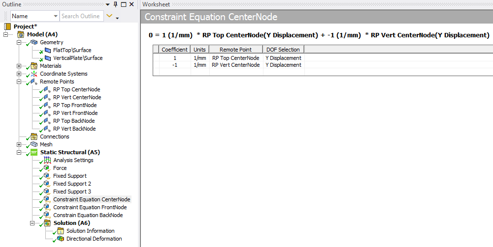
 Under Static Structural, insert a Constraint Equation. Right click to Add a row and fill out a node pair as shown below.
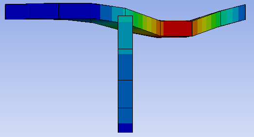
 Repeat for every node pair. You can see I have only done 3 node pairs but there are two more node pairs to get that centerline properly connected. Put in the last two and it will look much better!
 Attached is an ANSYS 2021 R1 archive.
Methods that are very quick and easy to implement (such as a revolute joint between the two edges) do not work on a local node-to-node basis. A joint will bring all nodes on one edge to a center point to connect to a center point that is connected to all the nodes on the other edge. This will have a similar effect, but if some localized forces are present, for example, on the front edge of the top plate, the error in using a joint will be revealed.
March 20, 2022 at 2:26 pmSubscriberHello peteroznewman, and thank you for the quick reply.
I hope there is another way, since I upload here a simple example. My real model is much more complicated with thousands of points mesh at the edge that I need to release and with your solution I need to create a remote point with a constraint equation for each node.
March 20, 2022 at 3:17 pmSubscriberHello Diana I created a hinge for displacements in the Y direction, whether they be upward or downward, because you said end release. If the force is reversed, the Constraint Equations prevent the top plate from lifting off the vertical plate.
What is the actual physical reality? Is it frictional contact? If so, when the force is downward, then the vertical plate supports the top plate, but when the force is upward, the top plate will lift off the vertical plate and a gap will open up between the edge and the face. If you have this condition, then it is easy to automatically create all the frictional contacts between all the edges and all the faces. Create two named selections: one with all the edges and another named selection with all the faces. Create one frictional contact between one edge and one face then use the Object Generator under the Automation tab to create all the other frictional contacts for all the entities in the named selections.
Note that if you do this, it is better to NOT split the face of the top plate, but rather have a single face. That will be on the Target side of the frictional contact and the edge will be on the Contact side of the frictional contact. Here are a couple of videos on the Object Generator, which does not work for nodes and constraint equations. The first video is mine.
Are you free to share your model on this public site? If so I can take a look at it.
March 20, 2022 at 6:09 pmSubscriberHi ,unfortunately, I can't share the model because of the policy of my workplace. I can explain the physical problem in this way.
Imagine to have a metal box like this one
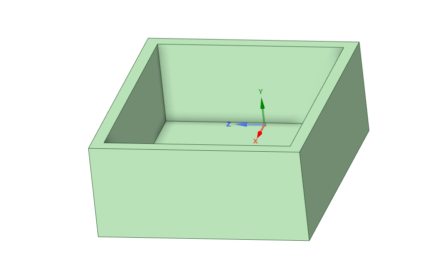 and now you want to add a metal cover but you can connect the box and the cover with an external fillet weld like this.
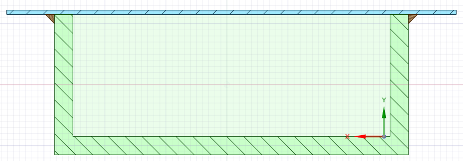
This connection can fix the translation in all directions, but not the rotation. I want that the cover can deform in this way
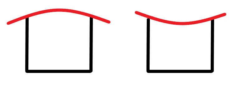
so is like having an end release of the rotation at the top of the wall box.
In another FEA software that we have is possible to release the rotation of a single mesh element, and I'm trying to do the same here in Ansys.
I tried your first option and is correct, but it could be difficult to replicate thousands of times because I saw that the Object Generator doesn't work with the FE selection and I can't crate the remote points automatically.
March 20, 2022 at 6:49 pmSubscriberHi Diana I have created a lot of models with fillet welds. Is the weld full length or is it a spot or stitch weld?
One method is to create the triangular solid body of the weld fillet. By using groups or named selections, you can automatically generate Bonded Contact between the faces of the weld fillet and the sides of the box and the cover. This would work even if the box and cover were shell elements instead of solid elements.
This creates a realistic connection between the box and cover because the weld fillet is not a perfect hinge and does provide some rotational stiffness depending on the length of the fillet weld.
Here is an example to create those fillets in SpaceClaim.
A different design that may not work in your case if the cover has to be cosmetic or smooth is to put tabs on the top edge of the box and slots in the cover. The welder then just melts each tab into the slot. This is easily modeled for shell elements. Just have the midsurface of the box have the tabs protrude up to the midsurface of the cover. No slot feature is needed in the cover. Shared Topology in SpaceClaim finds where each tab touches the cover and the mesh holds the two parts together. This takes less effort than creating the weld fillets if you switch to that design. Four years ago I used Bonded Contact to do something similar.
March 22, 2022 at 10:15 amSubscriberThank you for the suggestions. I'll try to model the weld in this way.
March 22, 2022 at 11:35 amSubscriberGood luck!
-
January 16, 2023 at 9:17 am
Xabier Aramendia
SubscriberHi @peteroznewman,
Reading various post related with the welds, I conclude that you are the person that most can help me.
I am developing a mechanical calculation tool for fatigue evaluation of welds subjected to vibrations. For that, first of all, I have to obtain a correct procedure or technique model to see the distribution of the forces suffered by the welds. I want to know the forces that suffered each node or element of the weld. For example, if I have 2 plates welded in 90 degrees (i.e. forming a T, with two welds),I apply a tensile force (200N for example) on the vertical part and if I fix the two ends of the horizontal piece and I define that two plates arent in contact (i.e. all the transmision of the forces is through the welds), each welding have to transmit 100N (simetric). So, it would be interesting to obtain the forces that suffer each element or node of the weld. Taking into account the model, I decided to define pieces as 2D plates, and with a flexible behavior and plane strain.
I am trying to obtain it, but I dont achieve it. I would like to obtain the forces that suffered each node, and logically, that the sum of these values results in 100N.
I have tried defining the each weld, and each plate as different parts, and defining some contacts between them. Bonded between the welds and each plate (all the forces from here), and nothing between the 2 plates (any contact, so there is no force transmision there).
From the other hand, I also tried doing it in only 1 part. If I define the 2 welds, the vertical part and the horizontal part in (all in 1 part), force reaction is null. I also define paths in the interested geometry (joint of the weld and the plates) and then introduce User Defined Results with ENFOY expresion in that path, but this doest give us the force of each element or node of the weld (gives the force in each point of the path, so it depends on the number of sampling points), so the sum is not 100N.
Can you help me please?
Thank you very much!
Xabi
-
January 16, 2023 at 9:23 amSubscriber
So, I dont know if the best option could be with:
-User Defined Result, and ENFOY expression with a defined PATH.
-User Defined Result, and ENFOY expression in the edge that joint the weld with the plate.
-Force Reaction in the edge that joint weld with the plate.
But what I know is that the sum of the values obtained there (in one weld), have to be half of the apllied tensile force.
Viewing 7 reply threads- The topic ‘Internal end release of plate elements’ is closed to new replies.
Innovation Space Trending discussions
 Top Contributors
-
peteroznewman
 6515
6515 -
scabo
 1906
1906 -
Dennis Chen
 1463
1463 -
javat33489
 1309
1309 -
Shyam Prasad V Atri
1022
Top Rated Tags
© 2026 Copyright ANSYS, Inc. All rights reserved.
Ansys does not support the usage of unauthorized Ansys software. Please visit www.ansys.com to obtain an official distribution.
-