-
-
February 17, 2022 at 12:21 pm
gogogog
SubscriberHello,
I am new to lumerical Charge. I wonder where is the space step of the simulation specified in charge? I only see "min edge length" and "max edge length" .The time step is clear in the transient simulation. The problem is I need to know also the space step in order to calculate the CFL stability condition .
Thank you in advance.
February 17, 2022 at 11:05 pmkghaffari
Ansys EmployeeHi Are you referring to the mesh size? This is determined in the mesh tab of the solver through the min and max edge length globally, or through local mesh constraints. Once you set up the simulation you can click on mesh (in the UI) to generate and visualize the mesh for your structure.
More information about mesh settings in CHARGE can be found here (please go to the mesh tab section).
I highly recommend looking into the CHARGE course provided on Ansys Learning Hub for getting started with the solver quickly.
Best regards
February 18, 2022 at 6:25 amgogogog
SubscriberThank you for the reply. I am referring to the mesh size. The charge solver gives the possibility of specifying only the min and max triangle edge length, as you mentioned, and it generates it automatically with automatic refinements at different regions. But what I need to know is which mesh size is used by the software in every region of the simulation region. The size can not be viewed when you view the mesh, it is not explicitly written like 0.01 for example at the top and 0.02 at the bottom... Isn't it? Charge solver does not specify the "number" size of the mesh, only min and max.
February 18, 2022 at 6:27 amgogogog
SubscriberIn the same mesh topic, can I import a mesh file ? or export the mesh as a file to use it elsewhere? Does the software give these possibilities?
March 31, 2022 at 7:26 pmkghaffari
Ansys EmployeeHi Sorry for the delay. As you mentioned the mesh length values are not explicitly mentioned in the visualizer. However you can rely on the available data and script post processing to determine these yourself:
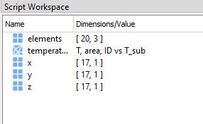
In the results provided, you can find elements and coordinates matrices (x,y,z). Size of elements correspond to number of generated mesh triangles and size of coordinates correspond to number of triangle points.
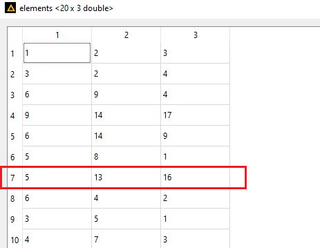
 For example, you might have 20 triangles and 17 mesh points. Elements indicate which of the 17 coordinates make up the mesh cell. For instance mesh number 7 is made up of the 5th, 13th, and 16th coordinates:
 You can find these values in the x, y, z matrices and calculate the edge length accordingly.
On your second question, we currently donÔÇÖt provide the ability to import or export mesh.
Best regards
Viewing 4 reply threads- The topic ‘How to know the space step to ensure stability in Charge ?’ is closed to new replies.
Innovation SpaceTrending discussionsTop Contributors-
5059
-
1770
-
1387
-
1248
-
1021
Top Rated Tags© 2026 Copyright ANSYS, Inc. All rights reserved.
Ansys does not support the usage of unauthorized Ansys software. Please visit www.ansys.com to obtain an official distribution.
-
Ansys Assistant will be unavailable on the Learning Forum starting January 30. An upgraded version is coming soon. We apologize for any inconvenience and appreciate your patience. Stay tuned for updates.


