-
-
February 7, 2022 at 9:02 am
azhao
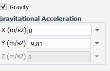
SubscriberI want to simulate a solid cone spray with a specified spray angle, spray velocity and spray mass flux. In order to save the computation time, I hope to do it in 2D. The following figure shows my setting for the spray nozzle.
February 7, 2022 at 1:51 pmNikhil N
SubscriberHello,
You should probably check two things.
1: As per the the settings you shared (from the velocity vectors), it looks like the injector is inclined at some angle because of which you might not get the symmetric flow pattern.
2: Please check the flow pattern of continuous phase as it interacts with the DPM particles and can affect the flow.
Let me know if this works!
Nikhil
February 7, 2022 at 2:22 pmazhao
SubscriberHello Nikhil Thank you for the answer.
1´╝î I agree with you that the injector might be inclined at some angle as I also did the same simulation with steady Lagrangian tracking and pulsed the calculated droplet trajectories, and found that the injected droplets only shoot to the right side. But the problem is that my settings for the group injectors are completely symmetric, only the velocity direction is changed for the first and last point, why would that lead to unsymmetric results?
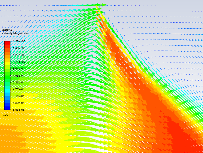
2, I checked the velocity vector distribution as shown in the following figure near the spray injectors. It is completely unphysical as the left side is flowing uprightwards with a very high velocity! I guess it is caused by the entrainment effect of the uprightwards droplet trajectories. But why does this happen? My boundaries of the fluid domain are all walls with DPM trap. The only momentum source is the injected spray droplets. Please correct me if I am wrong but I think there should not exist such large vortex structure...
Best regards An
February 7, 2022 at 2:25 pmazhao
Subscriber
I have uploaded my case as it is quite small. Could you please help me check if anything is wrong with the settings to cause such unsymmetric unphysical flow?
February 8, 2022 at 6:54 amNikhil N
SubscriberHello,
The vector image is not readable. Can you share some more images of the flow pattern?
Also, if the flow pattern for continuous phase looks unphysical, make sure that the steady simulation for continuous phase is well converged. What are the boundary conditions for the continuous phase? Can you also highlight the respective boundaries with an illustrative image?
For your information, Ansys employees are not supposed to download the attachments. However, if required, other forum members can pitch in and check the case file.
Nikhil
February 8, 2022 at 1:28 pmazhao
SubscriberHello Nikhil Thank you for the reply.
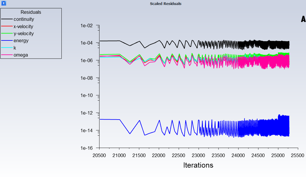 Please see the attached figure for the residuals of the steady simulation for the continuous phase, they are already at quite low level. I assume this means the calculation is well converged?
All the boundaries for the continuous phase are no-slip solid walls. And they are highlighted with black and red solid lines in the following figure, while the red line also indicates the thermal boundary condition with heat flux 10000 W/m^2K.
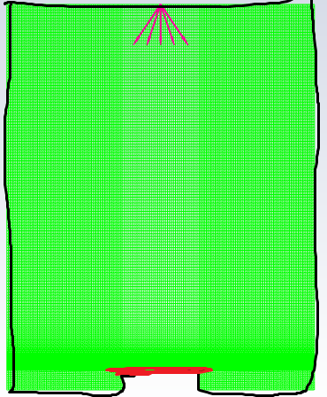 For the velocity patterns, I added the spray nozzle injection positions in the figure to make it more clear why it is unphysical.
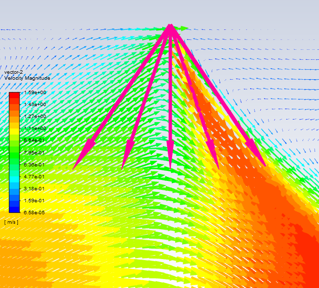 And the following figure shows the velocity vectors for DPM droplets.
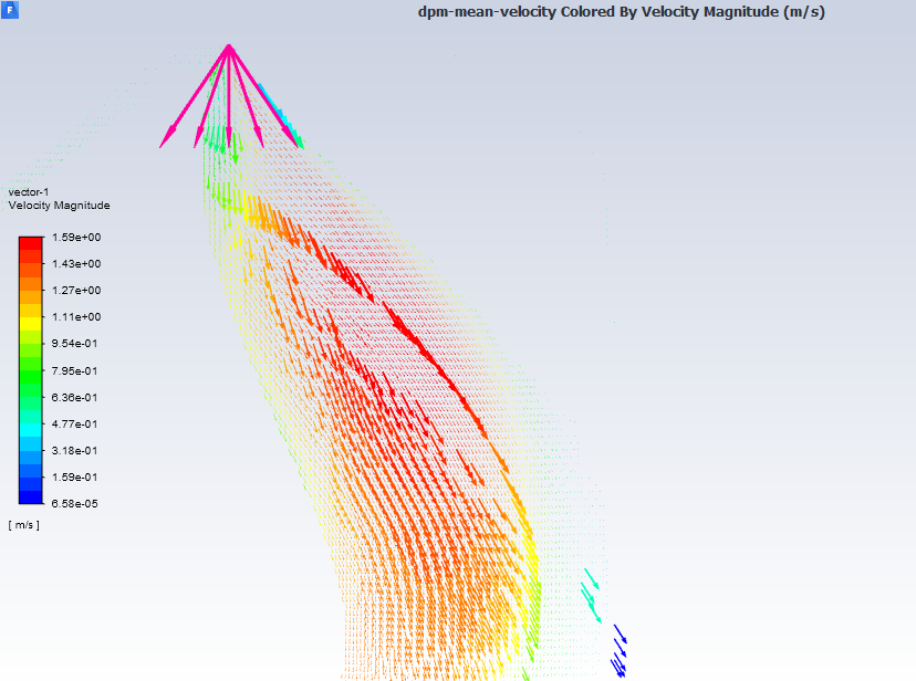 The turbulent kinetic energy distribution is as follows:
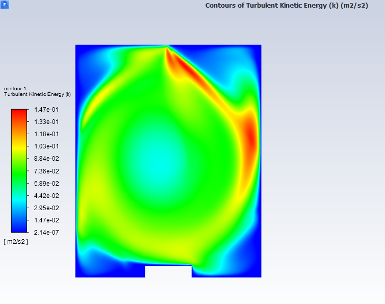 Extremely high turbulence dissipation rate is observed near the heated surface as follows.
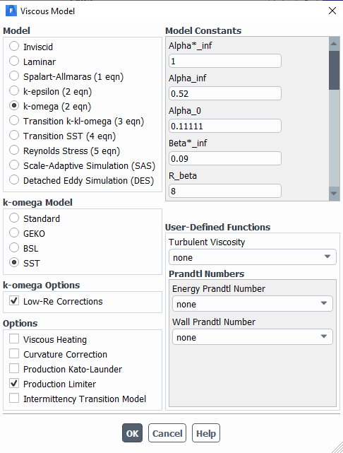
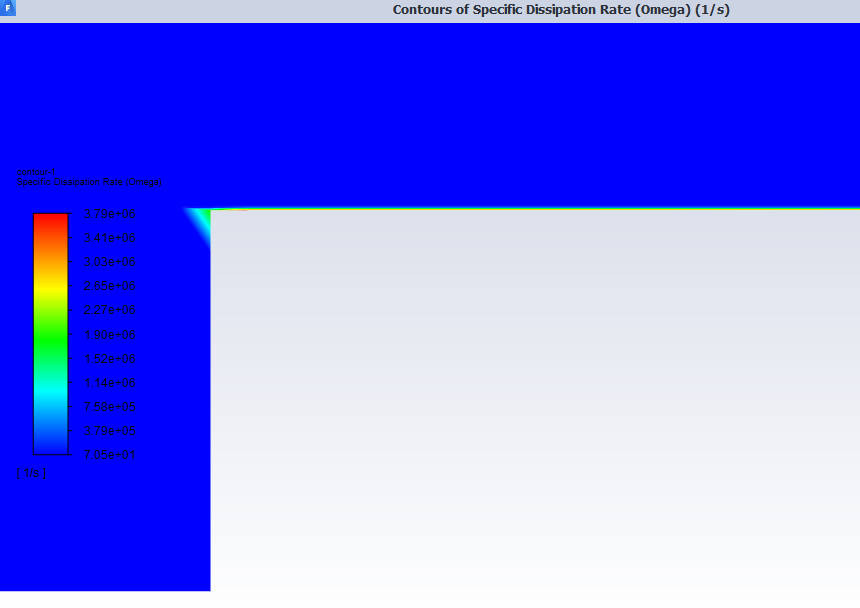 While the turbulence model settings are very common and as follows:
At last, the wall film thickness is also very strange, it is too ununiform and looks unphysical.
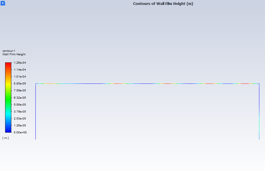 Could you please help me with it?
BR An
February 8, 2022 at 1:45 pmAmine Ben Hadj Ali
Ansys EmployeeYou are using group injection so the velocity distribution along X will change linearly from first to last point.
Momentum interaction is enabled so particles will influence the flow (only momentum) and consume of his energy. This will lead to the flow trying to counter-act that.
My question why are you solving particles unsteady and flow steady? (I think you can use Eulerian Wall Film if you just want to keep track of the film particles being trapped by a wall but you do not want to use transient particle tracking) Any buoyancy effects for the continuous phase?
February 8, 2022 at 4:38 pmazhao
SubscriberHi, DrAmine Thank you for the reply.
DrAmine-EDIT: removed screenshot from help.
I agree with you that Eulerian wall film model should satisfy my requirement, but it is only available in 3D. The reason I want to do it in 2D is that it could save a lot of computing time in studying the influence of different parameters.
About the reason why I solved particles unsteady and flow steady. this is due to the restriction that the liquid film boundary condition and the particle wall heat interaction option can only be enabled when unsteady was selected for the DPM.
BR/
An
February 8, 2022 at 5:05 pmRob
Forum ModeratorNow the images have finally loaded I think you've got a classic case of a messed up flow field.
Droplets are injected correctly and head out in a fan shape at the top. They entrain gas locally and cool it down, and should fall fairly evenly along with the cooler gas
Warm air rises, and given the hot plate is in the middle the plume should go straight up.
Except, the plume going up meets the injection coming down, and rather than remaining nice and symmetrical the two jets/flows will interact such that they don't directly contact each other.
Please post the temperature field and plot a contour of each of the flow velocity magnitude, vertical velocity component and temperature. I think I know what you'll post but need the images to check.
February 8, 2022 at 5:53 pmazhao
SubscriberHi Rob Thank you for the detailed explanation.
Please see the attached figures you asked about.
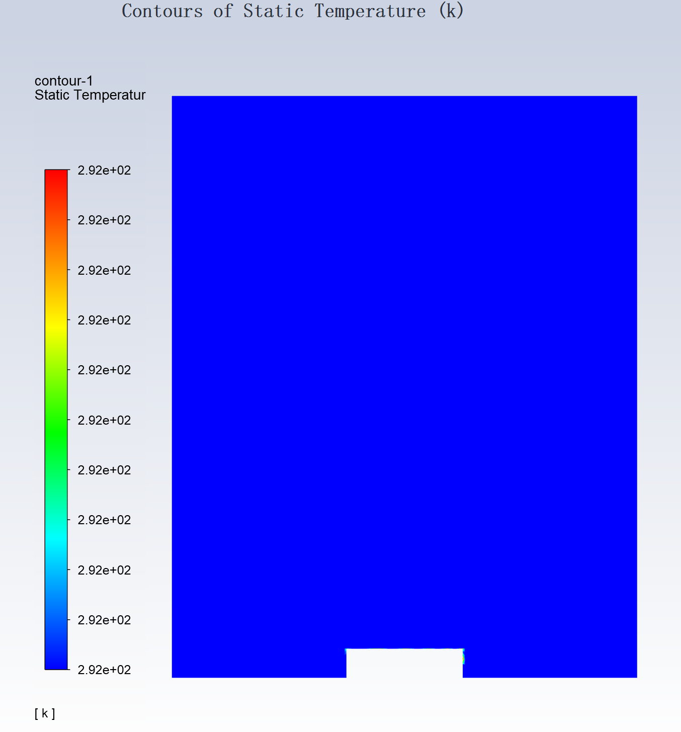
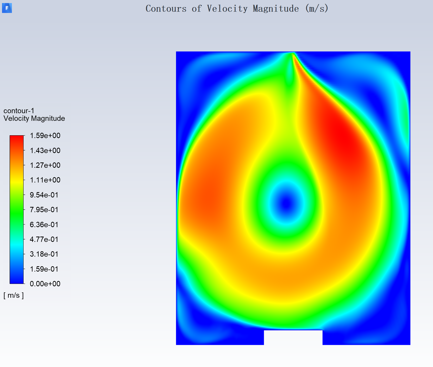
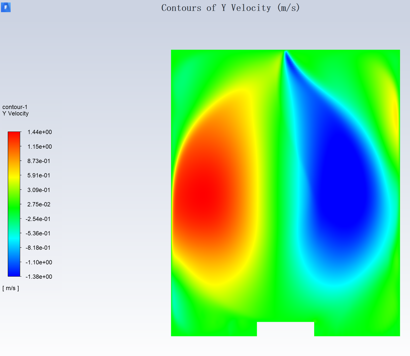 I am sorry I did not make it clear in the previous thread this problem actually occurs before I applied the 10000 W/m^2 K heat flux. Since at first before the spray reaches the heated wall I cannot apply the 10000 W/m^2 K directly on it, otherwise it will lead to super-high temperature. So this unsymmetric behavior actually existed when the heated wall is still 0 W/m^2 K.
I guess I got your point about the plume but it seems to me the plume velocity should be very low compared to the 12,1m/s spray injection velocity, as it is caused by natural convection. And because the air density is much smaller than the water density, the momentum of the plume would be much lower compared to the momentum of the sprayed droplets. I agree they will interact with each other and distort the flow path, but my case looks much more unphysical and unsymmetric even taking that factor into consideration.
An
February 8, 2022 at 8:23 pmazhao
SubscriberI have also uploaded my data file here in case it is needed.
February 9, 2022 at 8:20 amAmine Ben Hadj Ali
Ansys EmployeeIs your density temperature dependent?
February 9, 2022 at 9:21 amazhao
SubscriberNo, the density is not temperature dependent
February 9, 2022 at 10:17 amAmine Ben Hadj Ali
Ansys EmployeeSo how do you want to account for buoyancy effects if it is not?
February 9, 2022 at 10:23 amFebruary 9, 2022 at 12:06 pmRob
Forum ModeratorWhich may explain why there's no heat being added to the domain - the temperature is near enough constant.
OK, the spray is pushing mass down to the right, and as air must also refill the space it's going up on the left. This is where the 2d, 2d axi-symmetric and 3d results may differ as in 2d axi and 3d you'd probably see a spray region flowing downwards and air being entrained in behind it.
The result is numerically sensible, but physically unlikely in a real 3d system.
February 9, 2022 at 12:31 pmAmine Ben Hadj Ali
Ansys EmployeeI agree with Rob: "empty" space is filled back by air. Better to consider in 3D and also consider buoyancy effects (even if they are small) whenever there is heat additional to the system. Having a third degree of freedom in the space is meaningful here.
February 9, 2022 at 7:11 pmazhao
SubscriberThank you for the answers. I will try with 2D-axis-symmetric and 3D ones and come back to the forum after I got the results.
February 10, 2022 at 9:29 amAmine Ben Hadj Ali
Ansys EmployeeWelcome!
Viewing 18 reply threads- The topic ‘What is the correct way to inject a specified cone angle spray in 2D?’ is closed to new replies.
Ansys Innovation SpaceTrending discussionsTop Contributors-
3377
-
1052
-
1050
-
886
-
842
Top Rated Tags© 2025 Copyright ANSYS, Inc. All rights reserved.
Ansys does not support the usage of unauthorized Ansys software. Please visit www.ansys.com to obtain an official distribution.
-
The Ansys Learning Forum is a public forum. You are prohibited from providing (i) information that is confidential to You, your employer, or any third party, (ii) Personal Data or individually identifiable health information, (iii) any information that is U.S. Government Classified, Controlled Unclassified Information, International Traffic in Arms Regulators (ITAR) or Export Administration Regulators (EAR) controlled or otherwise have been determined by the United States Government or by a foreign government to require protection against unauthorized disclosure for reasons of national security, or (iv) topics or information restricted by the People's Republic of China data protection and privacy laws.


