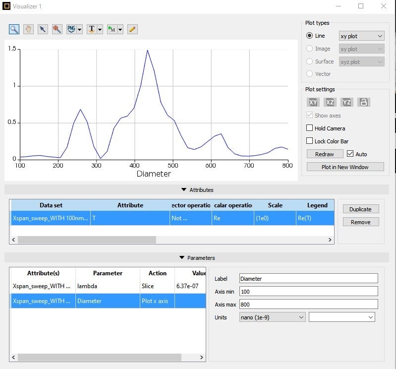
TAGGED: Lumerical-FDTD, transmission
-
-
February 1, 2022 at 4:02 pm
sagar
SubscriberFebruary 2, 2022 at 1:40 amKyle
Ansys Employee
There could be many different causes of this issue, as discussed in the post you linked. Could you please provide some more information about your simulation? Screenshots of the geometry with the sources and monitors would be helpful.
February 2, 2022 at 5:25 amsagar
SubscriberGeometry: My simulation is like, I have placed a parabolic pillar (dielectric material) just top of a bulk, divided by two parts; 100nm metal layer top of same dielectric material. pillar height is 1um and dipole is placed in the middle of the pillar. I have placed two monitors; one is 3D to get a far-field profile and one 2D (perpendicular to Z-axis) 250nm far from the pillar top to get transmission data. Xspan of pillar is 345 nm.
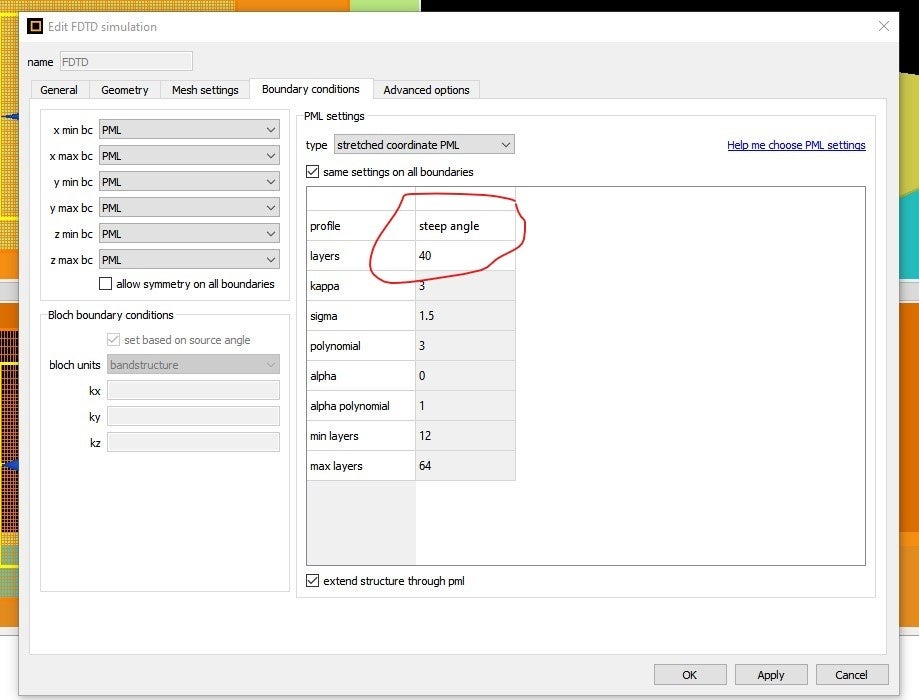
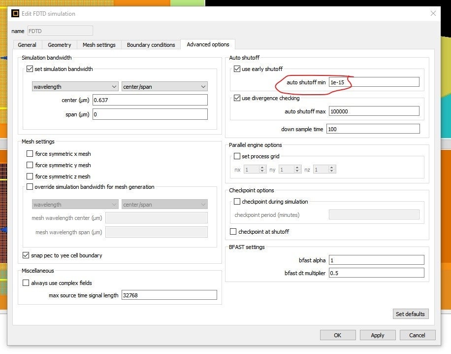
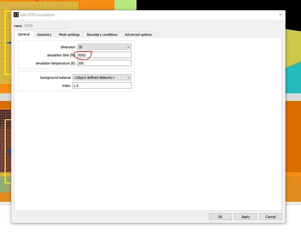
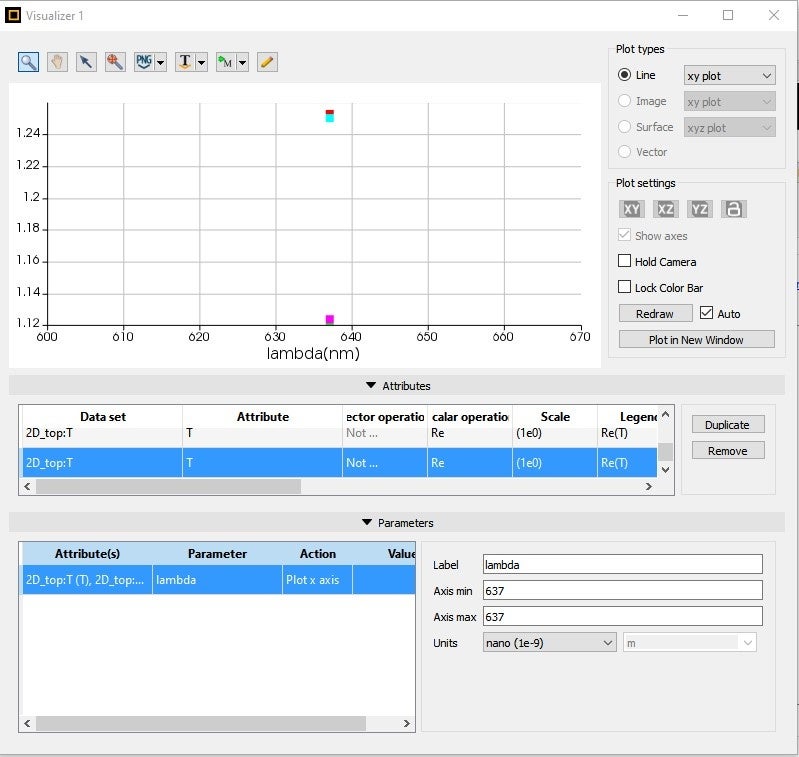
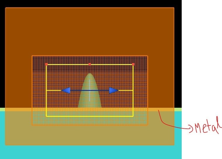 Simulation: As suggested in the discussion (/forum/discussion/comment/145787#Comment_145787) I increased the PML layer thickness to get rid of back reflection and increased the simulation time to 5000fs and changed the auto-shutoff minimum to 1e^-15, but still getting transmission more than 1. I varied these parameters but got no significant changes.
February 2, 2022 at 8:54 pmKyle
Ansys Employee
I would say this transmission value greater than one is probably happening due to the Purcell enhancement of the dipole source. This is the section from that post you linked about this issue:
Purcell Enhancement of Dipole Sources
The source power used to normalize transmission results when dipole sources are used is the power emitted by the dipole in a homogeneous environment. Due to Purcell enhancement, the power emitted by the dipole may change if it is placed inside a more complex environment. Note that this is not an error, because the actual power emitted by the dipole is changing.
You canrenormalize your resultsusing the ÔÇ£dipolepowerÔÇØ script command, which will return the actual power emitted by the dipole:
transmission("monitor")*sourcepower(f)/dipolepower(f)
Here the ÔÇ£sourcepowerÔÇØ command returns the power emitted by the dipole in a homogeneous medium (which is used to normalize the transmission results by default) and ÔÇ£fÔÇØ is a vector of frequencies. Note that in dispersive materials with a non-zero imaginary part of the permittivity or with a very high mesh density, the ÔÇ£dipolepowerÔÇØ command will return incorrect results, and a box of monitors around the dipole must be used to obtain the power emitted by the dipole.
More Information:
Dipoles in non-homogeneous materials
dipolepower script command
This page also has an example of this effect: Purcell factor of a microdisk.
Another possible cause could be some sort of divergence due to the metal layer intersecting the PML, but I think this is less likely. I would recommend first trying the renormalization method suggested in that quoted text above.
February 3, 2022 at 6:23 pmsagar
SubscriberI have done the simulation (diameter sweep of the pillar) for both cases with metal and without the metal layer, as you suggested to renormalize the transmission to divided the transmission value/ Purcell factor; as Purcell factor = Dipole power(f)/Source power(f). So I did the normalization for both cases (even without the metal transmission being less than 1). So I am getting plots like this.
 Hope this plot is clear. T(transmission), PF(Purcell factor), Renormalized_T(T/PF). Red and black lines are normalized T without metal and with the pillar.
And plot for T and renormalized T behaving quite differently. My main goal is to go with a diameter that will give the maximum transmission.
Here I wanted to compare the situation with metal and without metal, so I compared by doing renormalization in both cases. Is it right to do renormalization even if I do get transmission less than 1?
Another thing is there are many peaks are forming in transmission, are these corresponding to different modes? Like the first one is fundamental mode and so on?
(In this simulation I took fdtd region xspan, yspan and zspan 2, 2 and 3 um respectively, and stretched coordinate PML, steep angle with 40 layers.)
February 4, 2022 at 9:10 pmKyle
Ansys Employee
Here I wanted to compare the situation with metal and without metal, so I compared by doing renormalization in both cases. Is it right to do renormalization even if I do get transmission less than 1?
Yes, in both cases there will be a Purcell effect so the results should be renormalized. This is true in most simulations with dipole sources.
Another thing is there are many peaks are forming in transmission, are these corresponding to different modes? Like the first one is fundamental mode and so on?
This is more a question about physics than simulation, so I can't really answer that. You will have to rely on your understanding of the physics of your device to interpret the simulation results.
February 8, 2022 at 7:09 pmsagar
SubscriberThank you very much. I have another doubt.
Here my goal is to choose a diameter corresponding to which maximum collection of light would happen experimentally. Like we are getting maximum Purcell enhancement with metal at 415 nm, maximum transmission at 415 nm also but for renormalized transmission, I am getting maximum at 380nm. What will happen in the experiment, is it related to transmission or renormalized transmission? As Purcell enhancement is also very significant for many cases, as people want to get a higher Purcell factor, shall we select the diameter which has more Purcell factor?
February 9, 2022 at 11:05 pmKyle
Ansys Employee
The Purcell enhancement is a physical effect so you want to account for this in your results. If you want to compare results with different geometries the results needs to be normalized the same way. Different geometries will have different Purcell factors, so you should not renormalize each of the simulations results by the Purcell factor. Instead you should compare the transmission without renormalization. This way the results from each of the simulations will be normalized the same way (to the power emitted by the dipole in a homogeneous medium) so they can be compared. The transmission results will be greater than one, however this is okay if all you want to do is compare the different geometries.
Viewing 7 reply threads- The topic ‘Why am I getting transmission value more than 1?’ is closed to new replies.
Innovation SpaceTrending discussionsTop Contributors-
4613
-
1515
-
1386
-
1209
-
1021
Top Rated Tags© 2025 Copyright ANSYS, Inc. All rights reserved.
Ansys does not support the usage of unauthorized Ansys software. Please visit www.ansys.com to obtain an official distribution.
-
The Ansys Learning Forum is a public forum. You are prohibited from providing (i) information that is confidential to You, your employer, or any third party, (ii) Personal Data or individually identifiable health information, (iii) any information that is U.S. Government Classified, Controlled Unclassified Information, International Traffic in Arms Regulators (ITAR) or Export Administration Regulators (EAR) controlled or otherwise have been determined by the United States Government or by a foreign government to require protection against unauthorized disclosure for reasons of national security, or (iv) topics or information restricted by the People's Republic of China data protection and privacy laws.

