-
-
January 13, 2022 at 8:56 pm
Amir
SubscriberHello everyone,
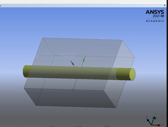
I am studying a case in which, air[warmer or colder than soil] passes through soil/ground and I am trying to monitor how soil temperature changes over time in some desired point(s).
January 14, 2022 at 11:53 amRob
Forum ModeratorRegarding the soil, solid is one approach. If you want to also model fluid movement then porous media may be suitable, but you then need to define all of those properties and work out what fluid is moving & how quickly. I'd suggest using a solid unless you REALLY want to model water running though the whole section: that'll not be easy.
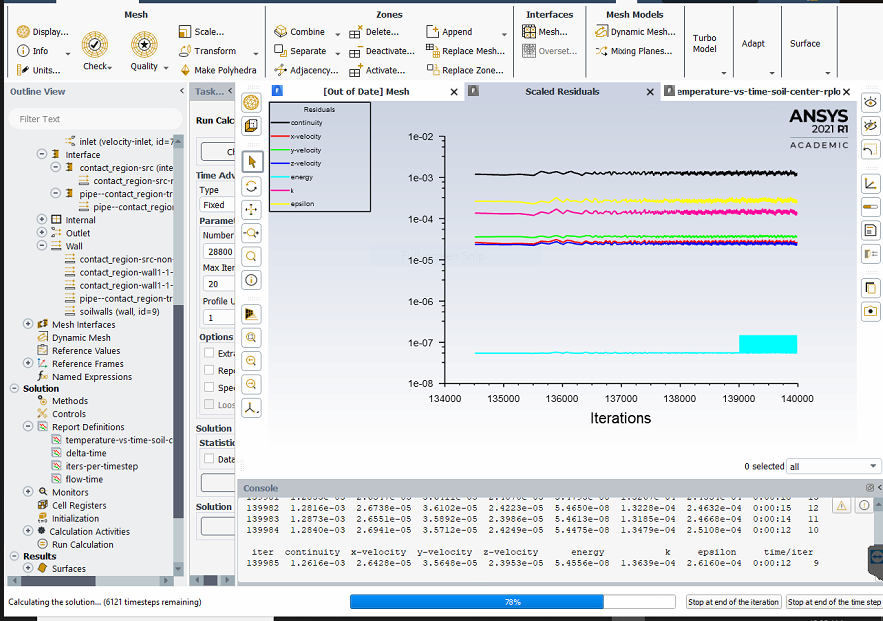
Time step looks high. How well is the model converging?
If you're pushing air though such that the temperature difference has a significant effect on the density then incompressible or full ideal gas may be needed. Given the temperature range is 0.6C and it's a forced flow system I suspect it's not necessary.
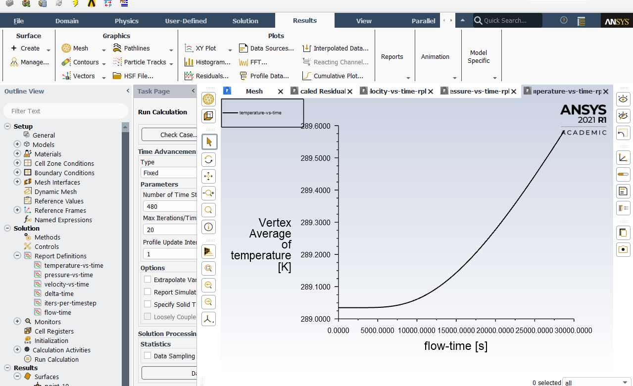
The graph looks sensible, but the low amount of heat transfer can also be attributed to the low cp of air compared to soil, air flow rates etc. There's a reason ground source heat pumps have many metres of pipework.
January 20, 2022 at 4:08 amAmir
SubscriberThanks . Well I am not specifically aiming to model air flow movement through the soil, but how soil temperature would change, however I am in doubt if there is actually any difference for modeling them.
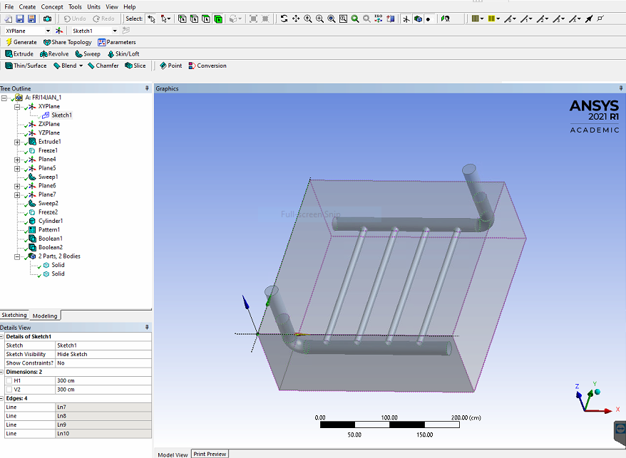
As you mentioned, the case is a ground-based heat exchanger and in real scenario, the pipes will be perforated tubes/pipes. I was planing to include this in geometry in next step(s)...
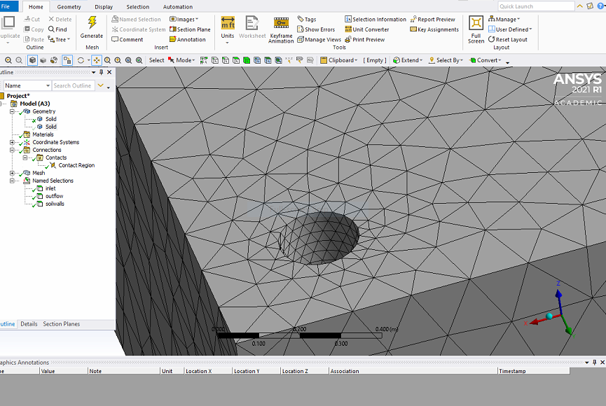
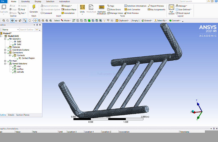
I am attaching some snapshots from another simulation I am running with a bit different geometry and I would appreciate any comments on that.
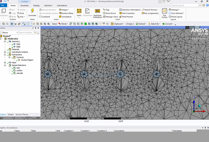
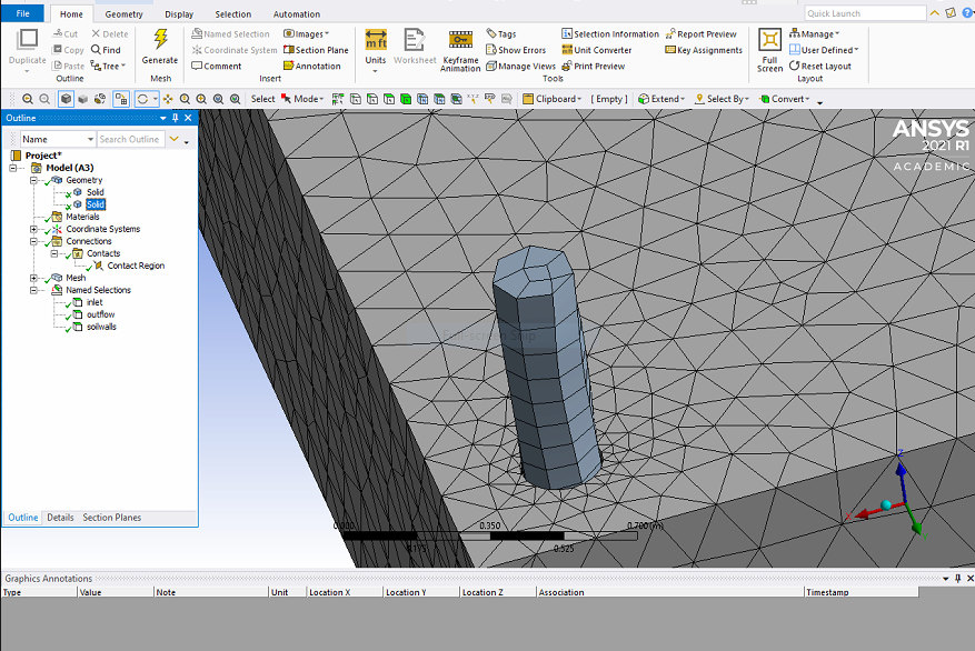
How important the mesh quality would be? I am not very sophisticated and had to keep it under 512k elements.
I set time step size to be 1 second with 28800 time steps and max 20 iteration per time step, the thing is that it has been taking so long (48 hours so far and its 78% done) and I am not sure if it is normal for this setup or not.
January 21, 2022 at 2:53 pmRob
Forum ModeratorLooking at the mesh I suspect the heat transfer from the pipe to soil is working at all: the cells should be a similar size at an interface and those surfaces ideally ought to be conformal. Please review some of the Fluent tutorials to get an idea of the mesh resolution required on flow channels.
January 24, 2022 at 5:17 pmAmir
SubscriberThanks for your comment on the mesh.
I tried to correct it. Cells seem to have similar size and sharing two nodes on the interface,can you please have a look to see how it looks?
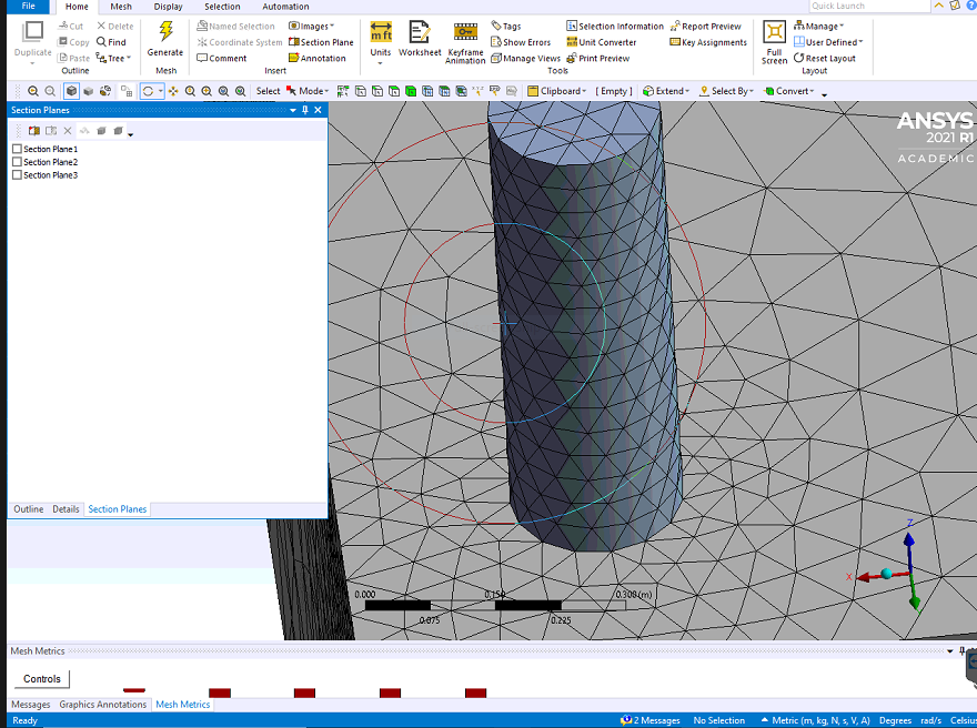
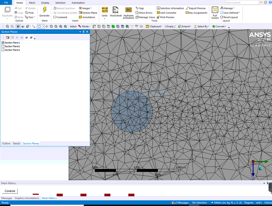
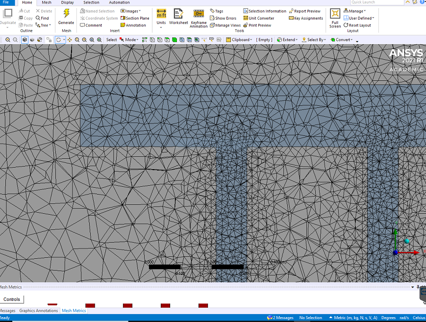
But this time I was not able to actually catch the interface in "mesh interface" tab. Instead, by selecting the surface of fluid domain underground(image is attached), I named that "INTERFACE" in meshing step, and then in fluent, it's BC was set to coupled wall with its shadow by fluent. Is that correct?
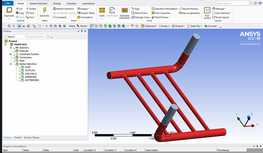
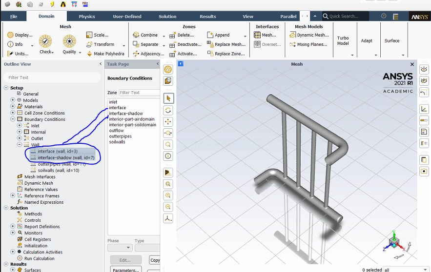
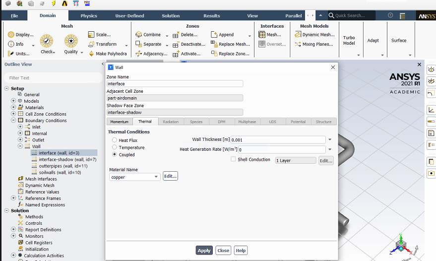
and finally, there was 1.6 degrees change in temperature at the center of soil/solid domain(from 289 to 290.6K). Before improving the mesh, there was 0.6 degrees. I am not sure if that difference was normal.
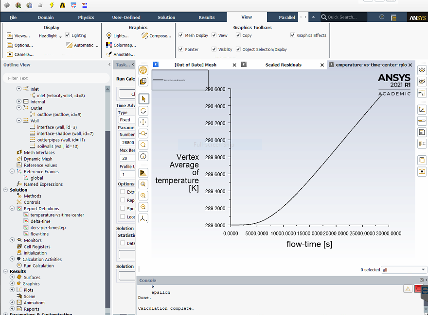
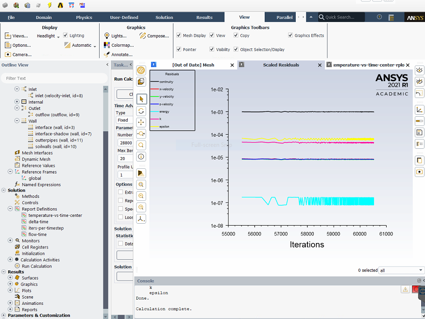
January 24, 2022 at 5:27 pmRob
Forum ModeratorIf you do a share topology step in SpaceClaim it should remove the nonconformal bits and make meshing easier. You then need to make sure you resolve the fluid bit enough to get the flow right.
I'll look again in the morning as the images aren't showing up for me (yet).
January 25, 2022 at 9:44 amRob
Forum ModeratorIt's working now.
Yes, for a conformal mesh you replace the interface pair with a wall & wall:shadow, these represent the two "sides" to the wall. I suggest calling it a wall in future, as "interface" in a boundary label will try and force a boundary setting in Fluent. It looks to be OK here but can cause problems with other mis-used labels, inlet being the main one that catches people out.
The temperature plot looks plausible, what are the soil external wall conditions?
January 25, 2022 at 6:27 pmAmir
SubscriberGot it, thanks.
And just to double check, I am attaching images of other walls BC to make sure I did not missed anything. Those labeled as "PIPEOUTER" are cooper with 1mm thickness and with BC being Temperature at 289K(~16 C).
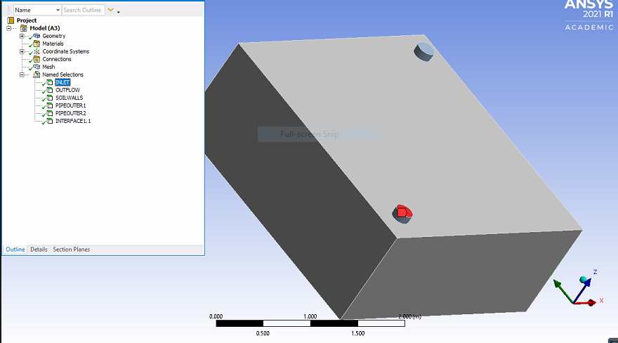
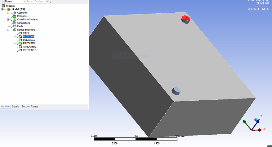
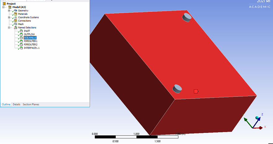
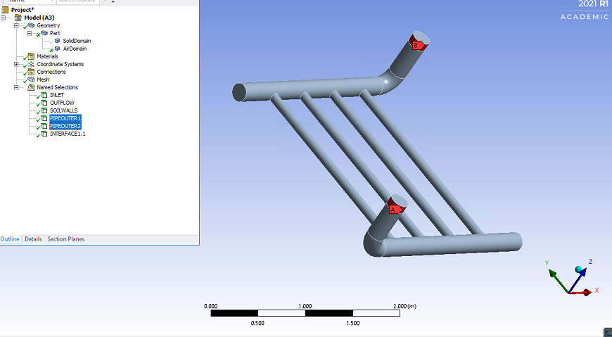
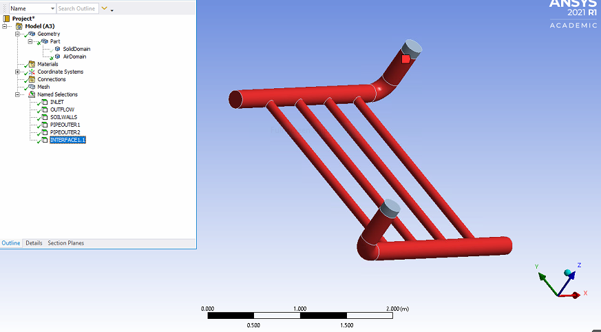
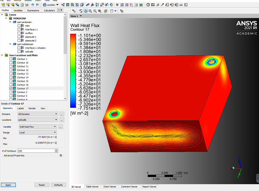
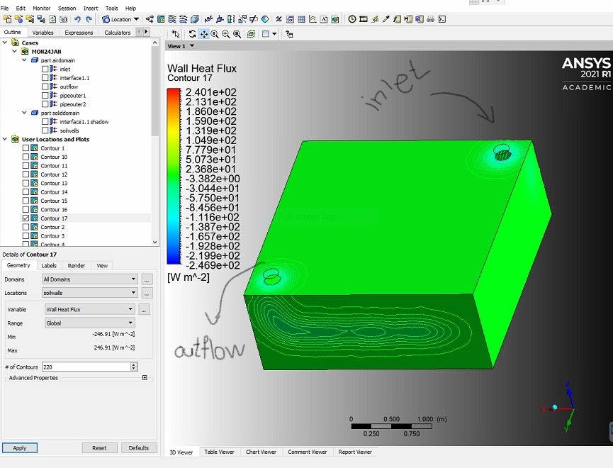
Regarding soil external walls, well eventually some sort of isolation material would be used for soil external walls, but so far I have been ignoring that material and setting those walls as "Temperature" condition, material is "soil" as the rest of domain, and at temperature of 289K. As like there is no other material. I was assuming no heat would reach to those walls at this level, However looking at "wall heat flux" contours, seems there is actually leakage.
I had a bit of difficulty understanding wall heat flux contours though, specially difference between Local and Global ranges. Can you please have a look at them too?
Thanks!
January 26, 2022 at 2:55 pmRob
Forum ModeratorLocal range is the value range on the surface(s) that you select. Global is over the whole domain. As the pipe is warmer than the soil heat is passing through the soil and leaving the sides of the domain. Use temperature boundaries with some caution: if they're too close to areas of interest you will artificially enhance/reduce heat transfer. Same goes for all boundary settings, but here it's the surface temperature being set.
Viewing 8 reply threads- The topic ‘regarding soil modeling and conjugate heat transfer between air and soil’ is closed to new replies.
Innovation SpaceTrending discussionsTop Contributors-
5064
-
1770
-
1387
-
1248
-
1021
Top Rated Tags© 2026 Copyright ANSYS, Inc. All rights reserved.
Ansys does not support the usage of unauthorized Ansys software. Please visit www.ansys.com to obtain an official distribution.
-
The Ansys Learning Forum is a public forum. You are prohibited from providing (i) information that is confidential to You, your employer, or any third party, (ii) Personal Data or individually identifiable health information, (iii) any information that is U.S. Government Classified, Controlled Unclassified Information, International Traffic in Arms Regulators (ITAR) or Export Administration Regulators (EAR) controlled or otherwise have been determined by the United States Government or by a foreign government to require protection against unauthorized disclosure for reasons of national security, or (iv) topics or information restricted by the People's Republic of China data protection and privacy laws.

