-
-
January 12, 2022 at 12:38 pm
tumulpurwar
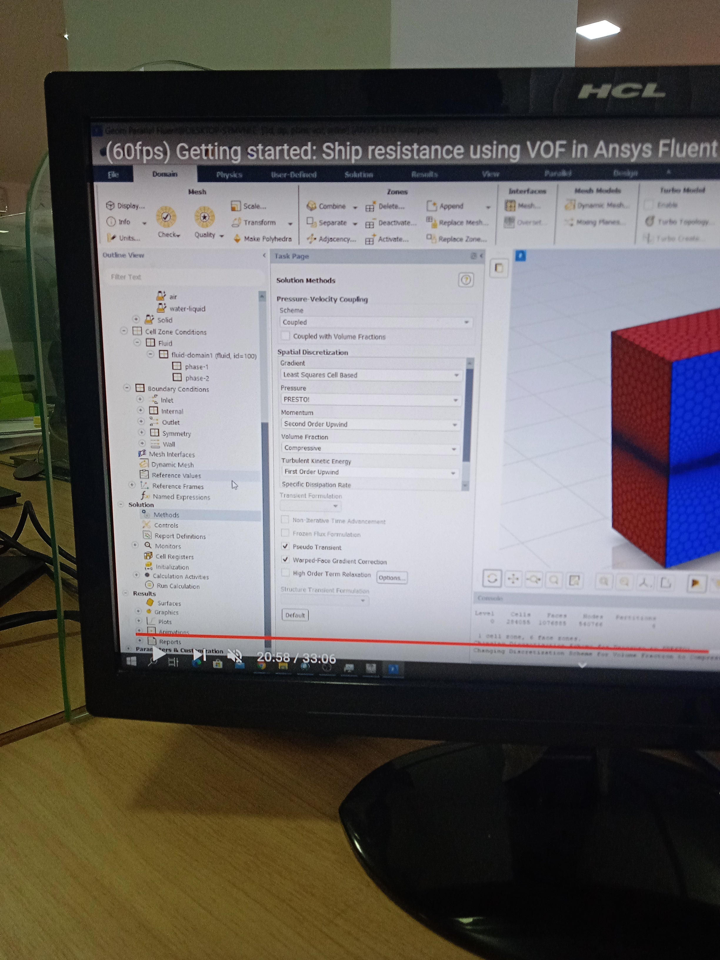
SubscriberWhy I am not able to see parameters of K (kinetic energy)& E(dissipation) parameters under solution tab in method option.
In this photo, they are but not in my case, it's photo from YouTube video.
January 12, 2022 at 2:13 pmRob
Forum ModeratorWhich turbulence model have you switched on?
January 14, 2022 at 1:10 pmtumulpurwar
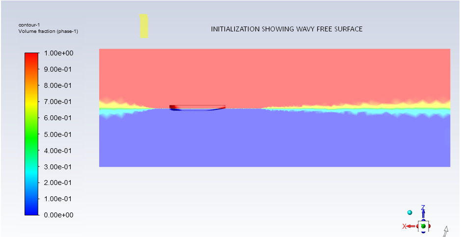
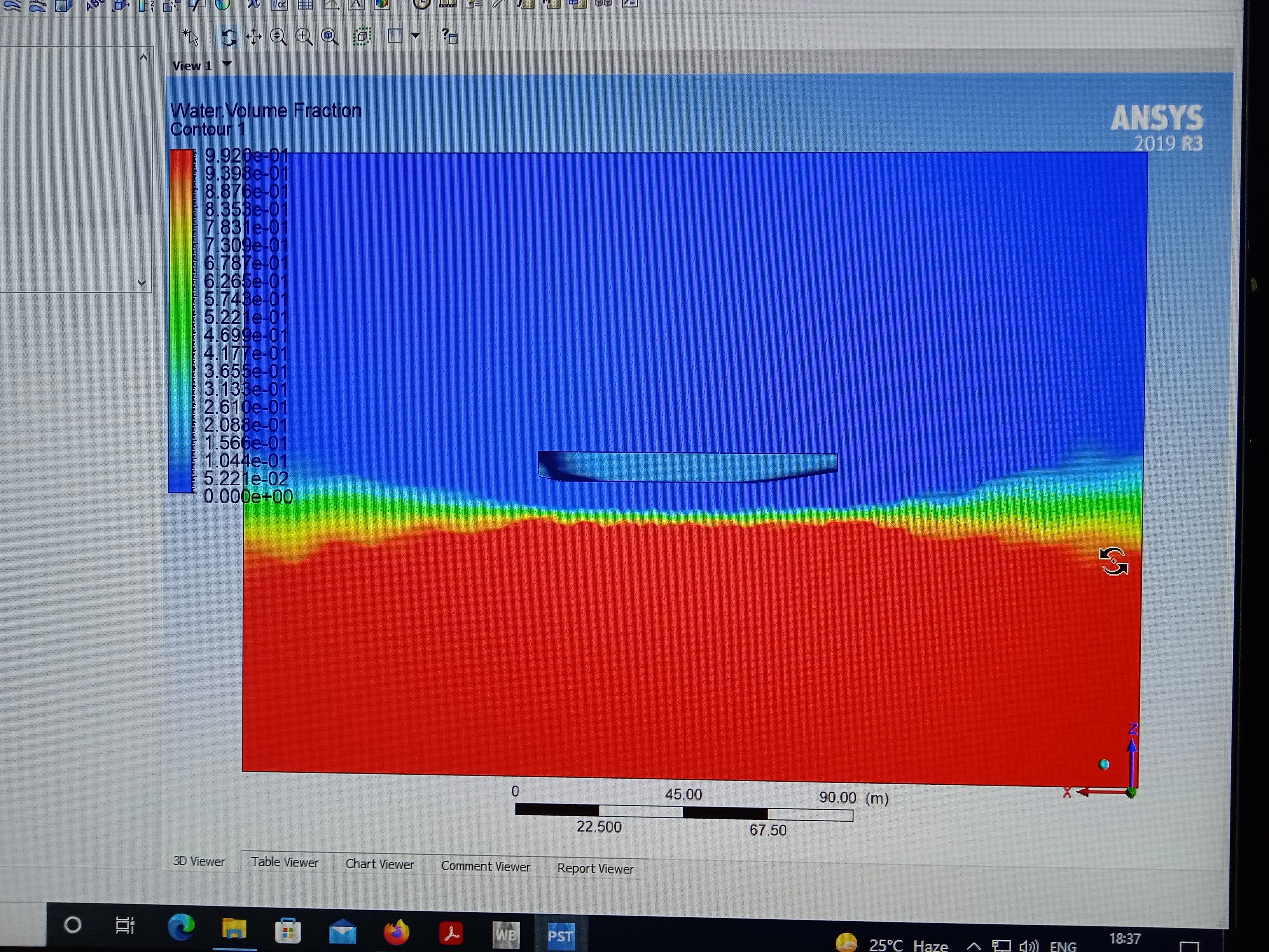
SubscriberK w, I was able to see, now thanks, but I have other serious question. When I put these two parameters freesurface level and bottom level under Boundary condition tab, after I do initialization, it shows correct contour, but after Run calculation, it shift my freesurface level just on opposite side. (See photo attached it shows freesurface in opposite direction, down of ship)
I also want to know, as I am less aware about vof, currently my case is of steady state, calm water(water not move, only ship move), and trim (or inclination of ship lengthwise is zero in my case) .
Do we have in vof, where we can play with dof of ship, like let it free to trim along lengthwise, is it possible? And how?
Thanks
January 14, 2022 at 5:07 pmRob
Forum ModeratorYou can have floating boats using the 6DOF solver. Looking at the above, did you set the outlet boundary too? That stops the water falling out of the domain.
January 14, 2022 at 6:44 pmtumulpurwar
SubscriberYes I set the outlet boundary also, there they just again wanted to put two parameters namely:
freesurface level and bottom level.
These two parameters I also put for inlet(whose value are same for both cases) ,except, in inlet I also added velocity value.
Well free surface should come above some finite value (say 3,6 meter above baseline) .
My baseline is passing through bottom of ship.
What can be the reason than, that my free surface go down of ship hull instead of up of baseline (or bottom of hull, 3.6 meter. )
January 17, 2022 at 12:19 pmRob
Forum ModeratorWhat did you set for the free surface & bottom level in the boundary condition panel? I've used the set up fairly recently and didn't see any problems: I assume it's converging well?
January 19, 2022 at 2:10 pmtumulpurwar
SubscriberCan you please tell boundary condition what you applied in your case?
For all 6 faces of fluid domain(mathematically cuboid) ?
I am facing problem, my calculation is not converging, I have used more fine mesh(mesh based on fault tolerant meshing).
May be problem in boundary condition.
I have used water tight vessel inside cuboid shape fluid domain.
My boundary condition are
Inlet (pressure based) (input parameter, 1) free surface,, 2) bottom 3) velocity at inlet
Outlet(pressure based) (input parameter, 1) free surface,, 2) bottom)
Watertight vessel (as wall, with no slip condition)
Rest other faces left of fluid domain(that is cuboid) as wall.
Tell me is this boundary condition are wrong? If yes than why?
Thanks
January 19, 2022 at 2:17 pmtumulpurwar
Subscriber
January 21, 2022 at 3:33 pmRob
Forum ModeratorVelocity inlet: open channel bc.
Pressure outlet: open channel bc
Sides were symmetry.
Seabed was wall
Sky was a symmetry plane.
January 22, 2022 at 12:22 pmtumulpurwar
SubscriberMay I know in lot of YouTube videos they are using inlet and outlet both velocity based.
Will it be wrong?
If I take my inlet pressure based than in multiphase tab, I have to select :
Wave theory (example First order airy or AIR WAVE THEORY).. But this theory states that water is treated as inviscid(negligible viscosity) .
I want to use real water(I mean practical water of real life, to simulate)
Than what theory under multiphase tab under inlet pressure based boundary condition I use?
I don't have half model of ship I am using full size model, so I am not using symmetric boundary condition, instead I am using SIDES, SKY, BOTTOM as wall with no slip.
Is my boundary conditions are wrong still?
How much yplus approximate I should take for calculating drag force for ship?
January 24, 2022 at 8:24 amtumulpurwar
Subscriber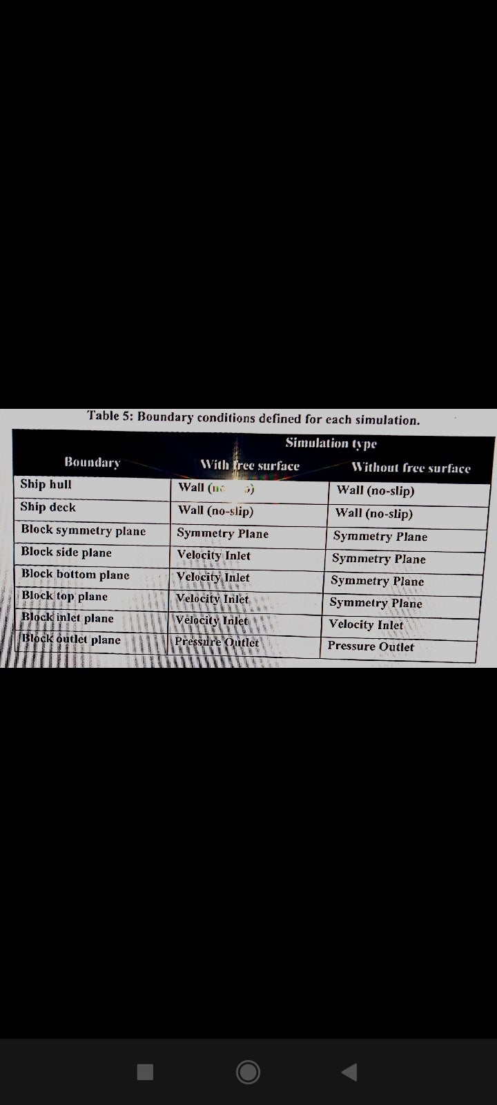 Can you tell , these boundary condition are correct for free surface case?
I also bit unclear what is free surface?
I am using VOF model, It means it contain free surface?
Right?
If I apply same boundary condition in my vessel, it's saying wrong boundary condition.. Why?
Can you please put bit some information?
Thanks
January 24, 2022 at 11:56 amRob
Forum ModeratorSide and sky will tend to be slip boundaries. Otherwise you're modelling the ship in a tunnel. That may be correct so I'll leave the choice with you.
I'm not sure why the definition above has so many velocity inlets. I tend to use velocity at the upstream end only, pressure at the top and pressure outlet downstream. Up & down stream boundaries use the open channel condition.
Where does the manual say about inviscid fluids for Airy? https://ansyshelp.ansys.com/account/Secured?returnurl=/Views/Secured/corp/v212/en/flu_th/x1-76300017.21.1.html
January 25, 2022 at 5:55 amtumulpurwar
SubscriberSide and sky will tend to be slip boundaries.... (It means I can use wall with shear zero)??? Or Symmetry under Type tab under Boundary Condition??
Airy wave is based over potential flow(whether manual say or not, but it's the basic principle over which it is based), it doesn't take into account viscosity, turbulence or flow seperation. (But I guess it's just limited to formation of waves as it is purely based over gravity, so thus doesnot consider effects of viscosity) but I guess when these waves interact with ship, our mesh will track these turbulence, viscous effect due to presence of turbulence model..)
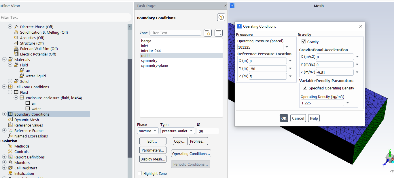
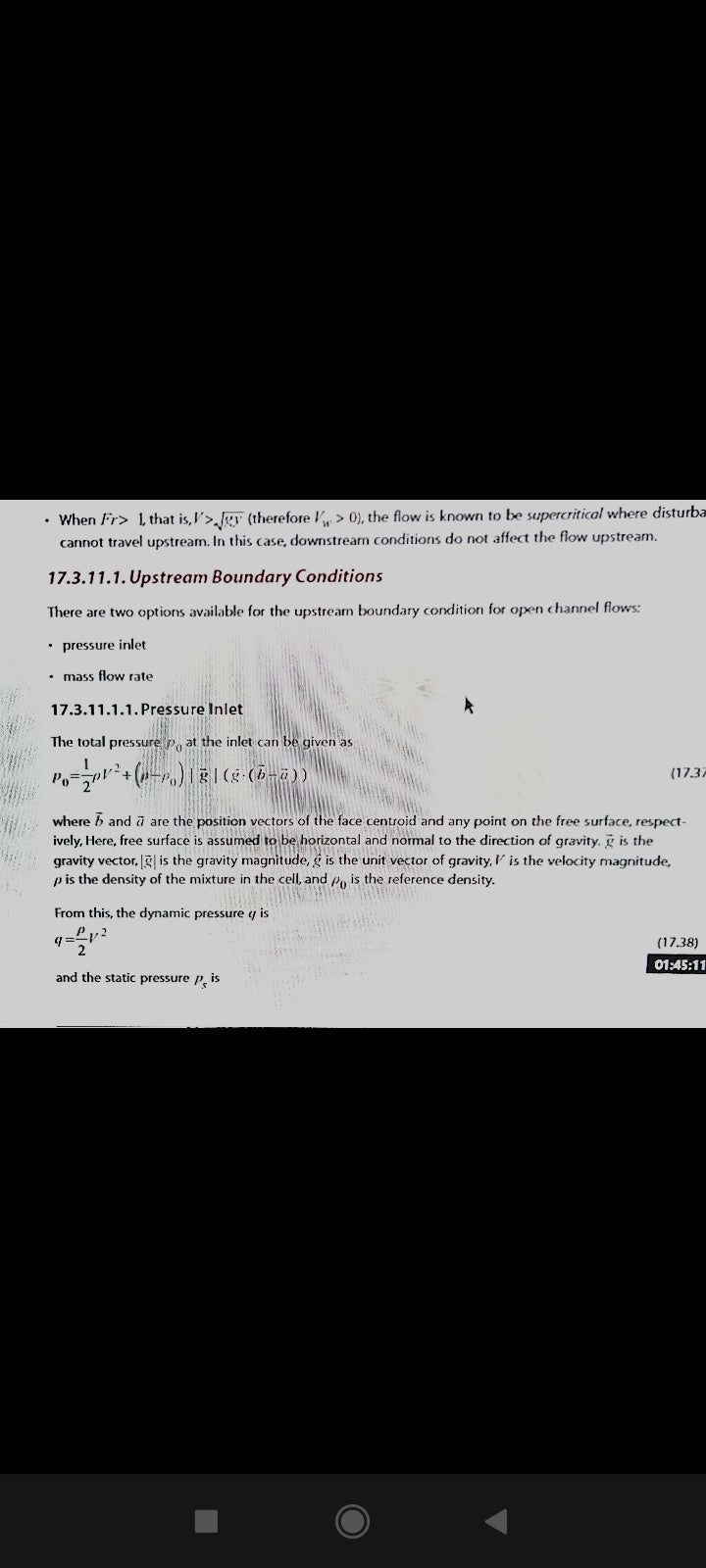
I also see in guide book, that for open channel, they don't have such thing, velocity inlet.
But you told you use velocity inlet for open channel case.
Can you clear out a bit? I am understanding the guide book wrong or something else. (I attached photo also)
One more thing in case of ship as, y+ varies along lengthwise shape of ship,what should be ideal y+ in case of ship?
I see people trying near 50 to 100?
Is not it possible to get y+ near 1 in case of complex shape like of ship?
Or is it that people doesnot care to solve viscous sub layer, as in case of ship, inertial force is greater in respect to viscous force, thus they trying solve for big Y+ values??
Thanks
January 25, 2022 at 6:04 amtumulpurwar
SubscriberOne more thing I came across, in guide book,
"All control volume must be filled with fluid phase. The VOF model doesnot allow for void region, where no fluid of any type is present".
As I have used my solid model ship inside tunnel(cuboid kind of shape in my case).
I used fault tolerant meshing, as it's easy meshing procedure, but under "Identify region" tab, we have to specify void and fluid region. So thus I specified it.
But as open channel doesnot allow void region, it means, I should subtract my ship from cuboid(tunnel)
To get fluid region without getting void region?
Thanks
January 25, 2022 at 3:21 pmRob
Forum ModeratorThe manual is fine from when I last read it, open the solver up and have a look at the options once the model is switched on: that and the tutorials are the best way to learn. Documentation is good background to get an idea of what ought to work. Given Chapter 17 isn't anything to do with VOF in the last few releases I wonder if that's an old version: the link I gave is 2021R2 which is has just been replaced (or is being, I've lost track) with 2022R1.
Slip wall & symmetry are more-or-less the same thing. I'd tend to use symmetry but may leave the sky open if the isn't enough space between the free surface and the top of the domain.
Void means vacuum, nothing to do with a "void" formed by a lack of cells. I suspect it's an explanation from back when people tried to just model the liquid and free surface without including the gas phase.
y+ ideally wants to be around 1, but with wall functions the limits are more relaxed. What is the intention of the project? If it's wave interaction then y+ may be less critical, if it's drag you need a well resolved boundary layer.
January 25, 2022 at 5:19 pmtumulpurwar
SubscriberWell, I need to calculate drag, and I am using Ansys license provided by my company but we don't have I guess so called ACP license where you get access to free resource, so if there is any other way I can access such information?
So I should use k w SST model for y+ =1 ?
Under fault tolerant meshing, when we need put boundary layer,(prism layer)
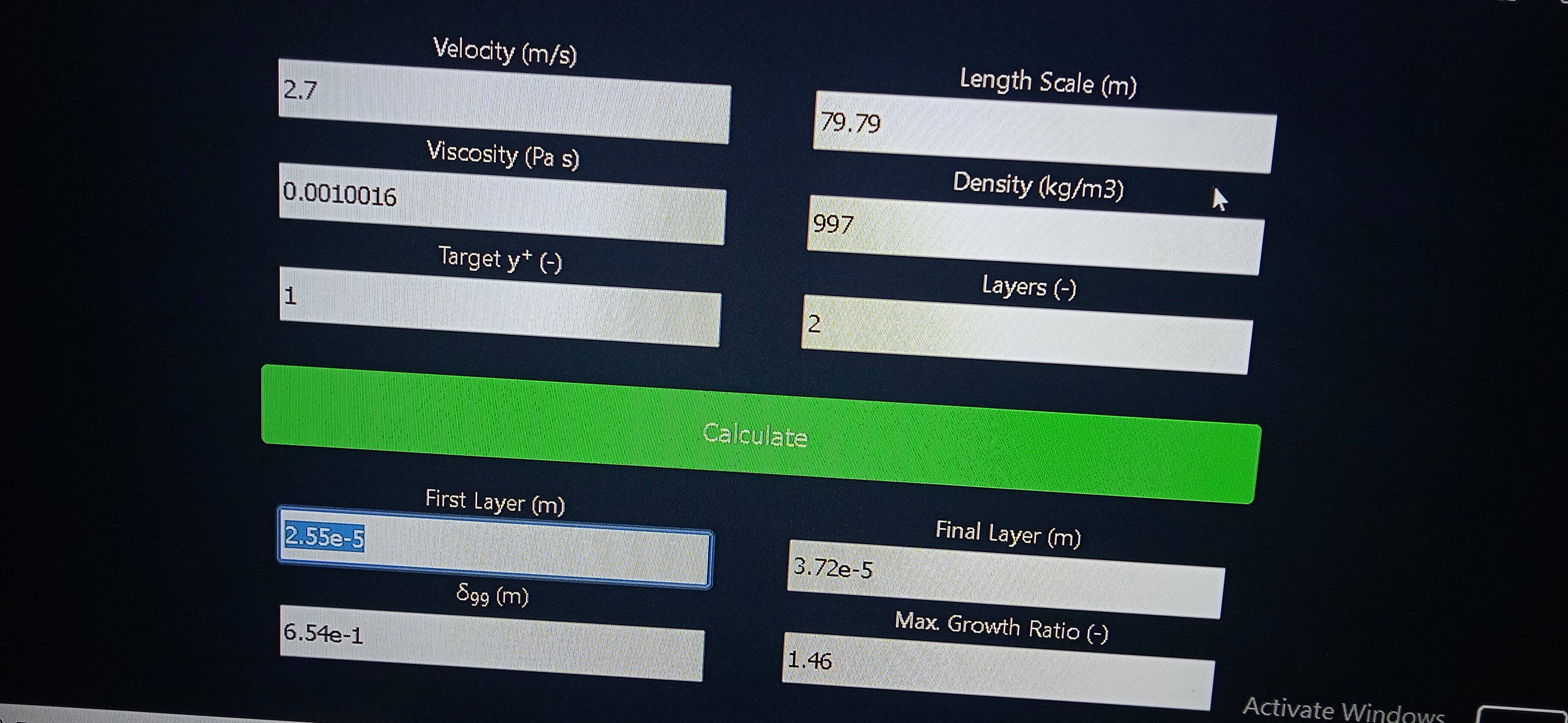
I use option "uniform" And put first layer thickness and Growth ratio and Number of layer, according to value calculated by online calculator from Cadence or fluidmechanics101 for flat plate boundary layer thickness.. ( from flat plate wall thickness, to get y+ = 1 , calculator calculate Number of prism layer = 35 minimum) When I put those calculated parameter, mesh get quite ugly, my cuboid (tunnel) get unorganised shape and form, kind of destroy from original cuboid shape( no more standard primitive shape)
I never saw any video in YouTube using 35 prism layer.. Can you track out where I am wrong. Can you see my first layer thickness is 2.55e-5(in calculator photo attached) , is not it too less?
Note: in calculator, I found first layer thickness just depend over wall shear, shear velocity.
Growth rato of prism layer depends over Number of prism layer used.
Growth layer according fluidmechanics101 should not be more than 1,3, to get the value of ratio below 1,3, I found I need to use atleast 35 prism layer.

I attach photo of calculator for flat plate thickness
January 26, 2022 at 9:43 amRob
Forum ModeratorIf you're using commercial software you should be entitled to support (assuming you're paying the maintenance or have a lease licence). They can advise in more detail than we can: we're region based so "we" might be "me" or could be one of my counterparts in your country/timezone.
Coming back to the actual problem. VOF and very high aspect ratio cells doesn't interact well. I tend to use smooth transition, and fewer inflation layers. The calculators are a good starting point, but you also need to apply some application knowledge: no point adding a near wall cell layer that's thinner than the likely surface roughness (eg critters & weed on a ship). The other aspect is getting the model working with a coarser mesh and then remeshing for a better result. So far, the boat has missed the water and you're interested in 6DOF: neither of those will benefit from a y+ of 1.
January 27, 2022 at 1:46 pmtumulpurwar
SubscriberThanks, I have two questions
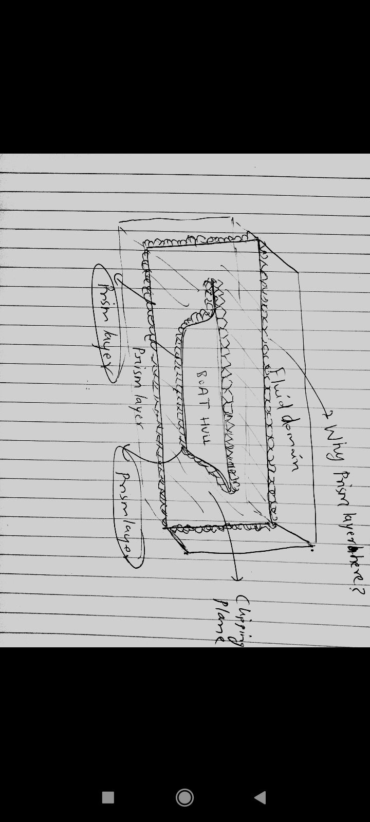
1) if you use watertight meshing or fault tolerant meshing of fluent, when I reach boundary layer tab, if I apply say 2 prism layer, why it apply to both, wall (in my case ship) and to cuboid outer edge also ( in my case fluid domain) ( I attached photo showing prism layer in both locations),.. I believe as area of interest is only ship, so prism layer should develop only in wall(in my case ship)... Sure in case when we do meshing from general fluent meshing, we have choice to select edges of area of interest (like in our case ship) outer edges only by choosing inflation layer over that specified edge.
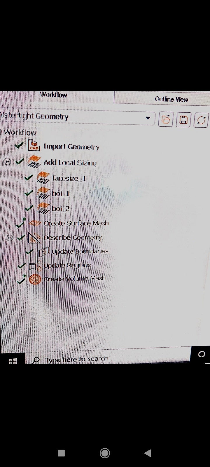
2 ) what is this "*" Asterisk sign suggest? (Photo attached)
January 27, 2022 at 2:11 pmRob
Forum ModeratorInflation will apply to all walls in the domain if you're using the workflows. Switch the sides & bottom to something else and change to walls or whatever in Fluent.
January 27, 2022 at 2:51 pmJanuary 27, 2022 at 4:18 pmRob
Forum ModeratorCheck either surface mesh or describe geometry. One of those gives the surface type definition: if it's a wall it'll get inflation on it if you're using the workflow.
January 27, 2022 at 5:42 pmtumulpurwar
SubscriberThanks Rob
January 29, 2022 at 12:37 pmtumulpurwar
SubscriberHello Rob
It's very stressing for me, as you have long time experience in CFD... Is there is any simple trick to know, what size mesh will be correct for my model.
I have run many times iteration with different mesh, and kinda got lost
I am unclear, to get mesh grid independence, which type of mesh we should try reduce(make it finer) every time?
Like in Watertight workflow.. There are meshing over surface mesh, volume mesh, prism layer, which one I need to reduce everytime.
I also want to know, my vessel is 80 meter long, it's taking too much time to do mesh.
Should I use froude geometric similarity to reduce my size of vessel?
Do you know if I use Adjoint solver(which doesnot work over multiphase model), as I am using single phase now to optimize hull by adjoint solver.
Do you know if there is any document for optimising vessel through adjoint solver?
Do you also have idea about ship resistance?
As ship resistance is made of friction resistance + wave resistance.
In multiphase, we get total resistance value? (Total drag)? Right?
And if we use single phase solver, without using turbulent model.. It will be than same as potential flow solver?
Normally potential flow solver based over laplace equation
And fluent based on RANS.
What's your comments?
Thank you
January 31, 2022 at 10:42 amJanuary 31, 2022 at 1:37 pmRob
Forum ModeratorShips aren't easy as you're trading off against hull size, multiphase, y+ and compute resource. Typically a poly mesh will give you the best meshing options (poly hexcore doesn't always work well with VOF if the cell size changes in the wrong place). Scaling often isn't overly helpful as you then need to scale back to "reality" and still need to resolve the flow: symmetry may help but otherwise you will need more cpu.
Drag is a function of all factors, so will include the effects of the liquid phase. Look at the force reports as it'll split the components out.
Turning turbulence off means you're running the system as laminar. Given it's almost certainly turbulent that's probably not a good idea.
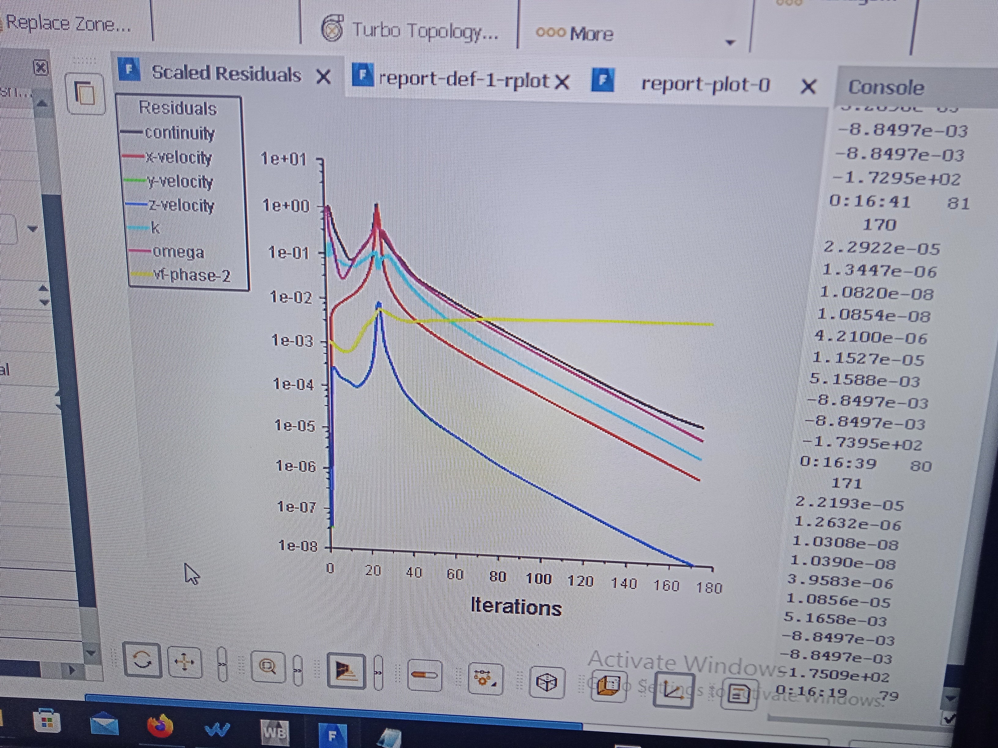
For the graph it's not usual for the VOF equation to behave like that. Check how the flow is behaving using the post processing tools and also check the mass flux.
January 31, 2022 at 2:30 pmtumulpurwar
SubscriberThankyou rob.. One more critical question, I want ask
As I want simulate my vessel in calm water(in naval field it's popularly know with name, calm water resistance test) .
In towing tank, we put our little boats with help of hydraulic rail , our little boat use to be towed with hydraulic rail, and than boat run at particular speed with help of this rail.
So in towing tank case, we are running our boat and water is in rest position.
Meanwhile here , we are moving water at particular speed & our boat is at rest, and we trying to simulate thus in CFD.
But i am not sure, as I have not yet touched degree of freedom of boat... Do i need use UDF tool, to set up dof for calm water test?
Normally pitch and heave are there even in towing tank offcourse, how I put these pitch and heave dof in my vessel?
Thanks
January 31, 2022 at 4:38 pmRob
Forum ModeratorIf you want to include pitch/roll/heave you'll need to use the 6DOF method and moving mesh. That'll account for the centre of buoyancy etc so the hull should remain in the water and bob around based on the model inputs. That's covered in the UDF Manual for the control part and moving deforming mesh section of the User's Guide.
February 1, 2022 at 7:18 amtumulpurwar
SubscriberMay I know rob, if I just put my boat in open channel, will my boat will drift from incoming fluid flow?
I mean if I have just put my boat directly in open channel, is software already considering that my boat is fixed in all directions(dof)?
And do we also need provide like surface tension Or any condition on free surface (air and water interaction plane in my case) ?
February 1, 2022 at 11:28 amRob
Forum ModeratorIf you build the mesh with no deformation or moving mesh it can't move. The shape (ship) can only change (move) if you add in models to allow this to happen.
Given the dimensions surface tension probably won't do much: consider the relative force from the motion to that generated by surface tension effects.
February 1, 2022 at 11:57 amtumulpurwar
SubscriberThanks rob
I have serious question.. I see lot of YouTube videos over ship resistance.
Some people putting reference values, some not for simulation in reference value box.
Some doing patching under initialization tab, some not.
What can be reason?
February 1, 2022 at 3:11 pmtumulpurwar
SubscriberHello rob
The big headache for me, and i dont find in google any answer for it
I get warning while doing Watertight workflow mesh... Under volume mesh (the last stage of mesh workflow), after finishing volume mesh with prism layer.... It gives warning with asterisk sign(*)
"A prism control was detected outside of workflow".
I checked, my prism layer are around fluid region walls only... Than why still it's giving warning???
Note in my case ship is wall and it's inside cuboid shape fluid domain.
All walls of fluid domain I made either symmetry or inlet outlet.
So only prism layer are around my ship which I want. (As my ship is defined as wall)
Than why still it is giving warning
February 1, 2022 at 4:06 pmRob
Forum ModeratorNot sure, what does the resulting mesh look like?
YouTube can be a useful resource, however, it's also got contributions that may be less useful, or very wrong. Wrong could be due to release updates. I would patch the water level into this sort of model. However if I didn't it'd still (probably) work but take a lot longer to reach a converged solution.
February 4, 2022 at 6:17 amtumulpurwar
SubscriberDear Rob
I just have General question regarding simulation time.
To run a ship model 80 meter long(length of ship) with fluid domain 3 times of length on back and 1 times of length on front & 1 times of length on side.
How much time it should in general take to calculate on hexahedral mesh(as multiphase don't run good over hexcore Or polyhedron)?
For me it took 6 hours to do calculation for 600 iteration, with residual near 10-3 for hexahedral cell for steady state multiphase.
Thanks Rob
February 4, 2022 at 11:57 amRob
Forum ModeratorSix hours for 600 iterations sounds slow. However, to speed up models you need sufficient cpu, RAM and licences to both maximise the hardware and parallel efficiency. I'm running a test model of around 1M cells and on two cores have done 6-700 iterations in about an hour on my laptop. For your machine check the RAM and cpu load: do NOT use hyperthreading and you may find you need to shut down YouTube.
As for how long a model should take. A steady flow should run in some hours (for me that's often overnight) with no more than 250-500k cells per core, and often nearer 100k cells per core. This also assumes sufficient RAM for the processes and nothing else on the machine. Virus scans, YouTube and the like can cause performance issues.
February 7, 2022 at 5:03 amtumulpurwar
SubscriberHello Rob
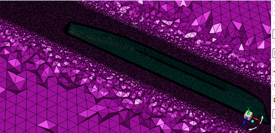
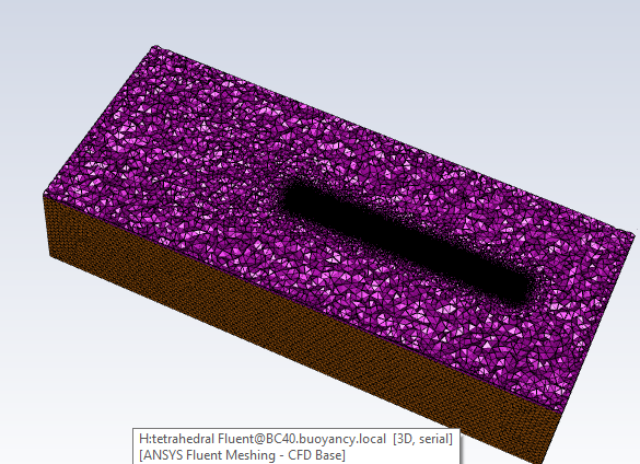
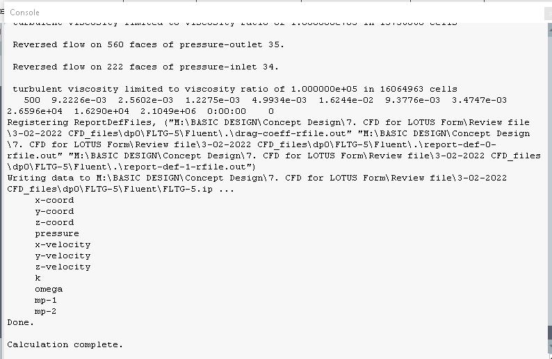
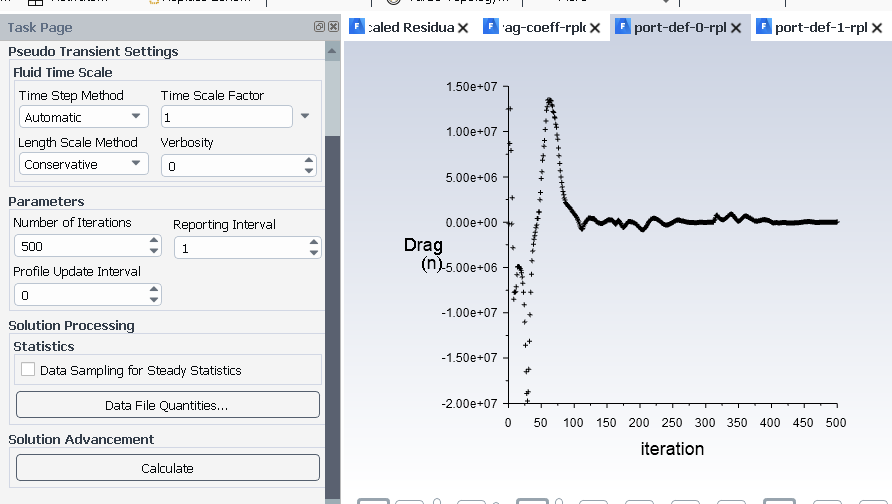
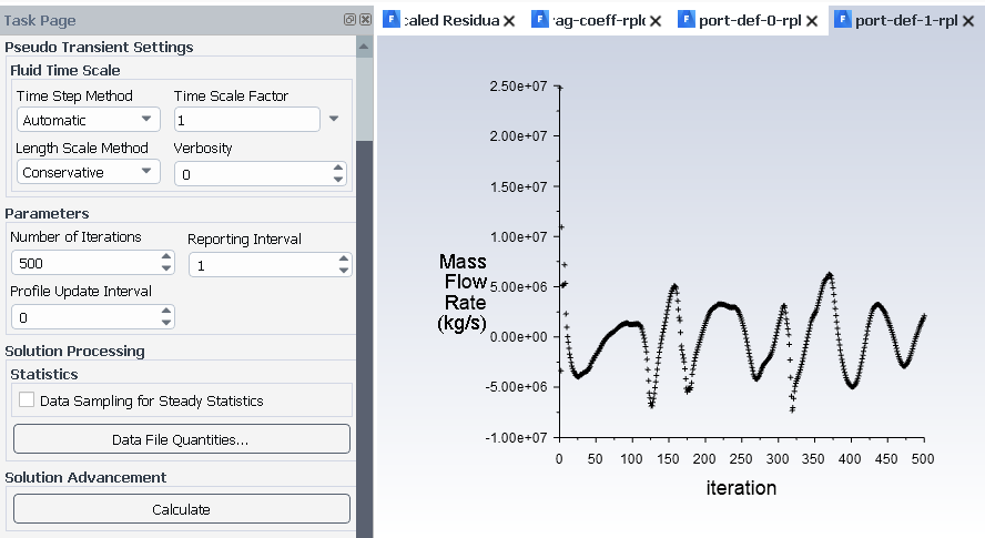
I used tetrahedral elements throughout,ran 500 iterations for 1 day, getting this results (photos below).
Guide book prescribed to use tetra or hexa for multiphase, so i tried using tetraheral this time,and produced 3 parameters as output(coefficient of drag, drag force ad mass residual for inlet and outlet).My mesh passed also skew and orthogonal criteria but still results especially mass flow rate is showing solution is not converged(there is Reverse flow also), earler while using hexahedral or more advance octahedral etc,it never gave problem of reverse flow for same domain..what can be reason, how to fix this reverse flow?
Mesh Size
Level Cells Faces Nodes Partitions
0 18838967 38197705 3493387 1
1 cell zone, 6 face zones.



February 7, 2022 at 1:22 pmRob
Forum ModeratorI expect the reverse flow is from the air space or far field on the water. It's fairly normal and you may need to view velocity components on the outer boundaries to find the issue.
18M cells wants to be running on 18-36 cores and you'll be wanting over 36GB of RAM, possibly nearer 54GB. Make sure interface anti-diffusion is on on the VOF panel.
February 7, 2022 at 1:48 pmtumulpurwar
SubscriberHello rob
Thanks for info.. But my big question is do you think these above are correct solution? As mass flow is fluctuating.
And in this case for boundary layer, if I choose smooth than only my orthogonal quality values pass, if I choose other option like "Uniform" It ever give poor orthogonal quality, I tried using "Uniform" Option and than tried filling empty boxes like:
First layer thickness
No of layers
Growth ratio
If I fill these value with general flat plate thickness calculator (like from fluidmechanic101) the value especially first layer thickness comes from calculator 2,55 x 10^-5,orthogonal quality comes poor, if I change value 10^-4, than orthogonal quality bit improve.
So it looks only "Smooth transition" Option works for me, to generate mesh with good orthogonal quality.
But with 10^-4 order first layer thickness, I don't get yplus after calculation near 1, they comes like 1500(too large value).
With smooth transition, user don't have control over first layer thickness.
As I am using Kw SST, I want value near 1 of y+
But I am bound to use only Smooth transition option under boundary layer, if use other option(say "Uniform", it ever gives problem of orthogonal quality to 0(very poor)
How should I control this?
Can you also tell what your experience says about fluctuating mass flow? As, it's fluctuating, it means our solution we getting still not correct, right?
Thanks
February 7, 2022 at 4:42 pmRob
Forum ModeratorIt's a transient model so mass flow will fluctuate, especially with VOF. If it's the steady solver VOF mass will still fluctuate as the solution will be partially transient.
Re the inflation and poor quality mesh, you need to understand what is causing this to fix it. Re the y+, use adaption to improve the near wall resolution, but remember it'll cost you cell count.
February 9, 2022 at 7:42 amtumulpurwar
SubscriberHello Rob
In my case,i want optimize my ship design:
Constraint: wetted area remain fixed(or also called ship displacement)
drag we want to reduce
I guess my optimization comes under multiobjective optimization?? As displacement is fixed ,but geometry can change to optimize drag coefficient value.
which tool better? Adjoint alone or Gradient base optimizer?
Note: i dont have RBF Morph
thanks
February 9, 2022 at 10:10 amRob
Forum ModeratorAdjoint will tell you what will help reach the objective, you then need a to make those changes. Note, one outcome is to move the hull out of the water so set the constraints carefully.
February 10, 2022 at 7:07 amtumulpurwar
SubscriberHello Rob
As i am unable to get correct y+ for k e model(between 30 to 300), i tried using adaptive mesh refinement in 2019 R2. i gave the range 30 to 80 under Register tab, and later than in Adaption control tab, i selected my new cell register(name in my case as can be seen from photo"yplus_star_0") & than i hit "Adapt" button...........after running 500 iteration in calculation tab, still getting high y+ , where i am doing wrong??
Note: i am doing it over my "ship" wall.I mean this adaptive refinement, as i want very fine mesh around ship
Can you also tell what kind of mesh is best suite for adaptive mesh refinement(currently my mesh is made of tetrahedral, due to limitation of multiphase).
In 2019 R2, it dont have Gradient based daption method, only contain two methods as shown in 2nd photo

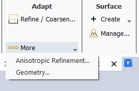
February 10, 2022 at 10:00 amRob
Forum ModeratorNear the hull I'd use anisotropic adaption, but you may need to adapt the entire boundary layer. If you're limited for cell count "normal" adaption may be more efficient for small areas. Don't use gradient as you'll want a y+ or VOF range to refine on. I strongly recommend moving to 2021R2 or ideally 2022R1 to take advantage of the improved adaption functions. That'll also give you full adaption of poly mesh which may reduce the cell count.
February 10, 2022 at 11:46 amtumulpurwar
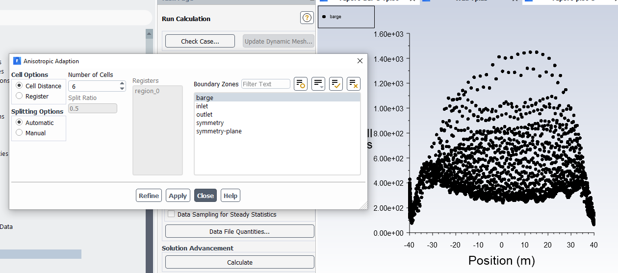
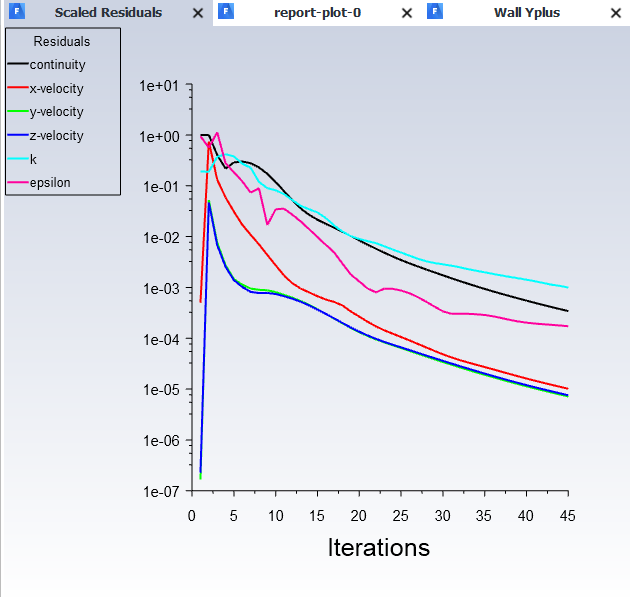
SubscriberHello Rob thankyou, i tried using anisotropic as you told, i changed my solver to just single phase for now to reduce long iterative time..first i should get correct y+ than i will go back to multiphase...currently Residual converged just in 45 iterations but even using anisotropic it giving high y+(see photo below)
Second photo showing solution converged in just 45 iterations.
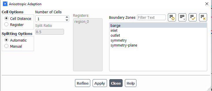
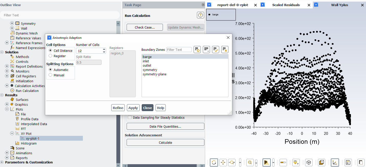
What to do with anisotropic further to get y+ between(30 to 300)??? The setting i used in Anisotropic adaption is below in first photo.i just let the default value remain and clicked Refine than Apply and than went to Calculation tab and ran the calculation.
Note:Limitations of Anisotropic Adaption-
It only works for hexahedral cells or prism cells............i used hexcore in my case for volume meshing


February 10, 2022 at 12:39 pmFebruary 10, 2022 at 1:54 pmRob
Forum ModeratorHave a look to see where those cells are. You then need to weigh up splitting the entire boundary layer or just a few localised regions. Equally, given the cell count limits run the model and optimisation but note the need for a higher resolution mesh in the report. Student is intended for you to learn on: for full projects you really need Research and parallel compute resources: I'd be throwing 2-300 cores at this model.
February 11, 2022 at 4:21 amtumulpurwar
SubscriberHello Rob
After increasing number of cells further from 6 to 12, i am getting quite better y+ value(photo below) in comparison to last y+ value (when number of cells were "6"), but still not what we expect for this simulation, i.e.(y+ under 300).
what split ratio i should give for current adaption?, Can you tell and what will be reason of choosing that particular split ratio?
Sorry Rob, i didnt understand your below statement
"for full projects you really need Research and parallel compute resources: I'd be throwing 2-300 cores at this model."
Why i need upto 300 cores, my current system is 4 cores, and still quite fast its giving results. Can you please explain.

February 11, 2022 at 5:18 amtumulpurwar
SubscriberHello Rob
increasing number of cells further from 12 to 18, Y+ improved more globally along length of ship, but not in local regions, how i use split ratio for local region, i didn't understand definition of guide book about split ratio,if you could explain it please in simple words(which base face they talking about).
i also want know, i want throw this model mesh once i get y+ below 300 in optimization tool, probably as my optimization is multi constraint, Gradient based optimization will be better for my case, i want optimize my geometry mesh by reducing drag or ship resistance...is there is issue if i refine with anisotropic adaption & later using optimization tool??? Are optimization inbuilt tool of Ansys are compatible with Highly refined mesh??(like that of with the help of anisotropic adaption??
February 11, 2022 at 10:42 amRob
Forum ModeratorTaking the various points:
Ships are big, and you need to resolve the hull, near hull flow and the free surface. That tends to require a fairly big mesh and transient solver. To avoid cell count constraints a Research licence (commercial in my case) means I can use as many cells as I need rather than 512k. With more cells I can benefit from more parallel and as I'm impatient (and expensive) I gain by using a lot more cpu.
You need to refine the mesh to y+, and the free surface. I'm less sure about the need to resolve the velocity gradients as I suspect they'll be near the hull and free surface so get dealt with as a side effect of the other mesh refinement tasks. If not then flow field gradient refinement may be useful.
The optimiser will use gradients of change to propose (and if allowed) make changes to the shape. I don't know if the mesh refinement and optimiser will work well together: check the documentation for limitations. The level of mesh refinement won't effect the optimiser, however it will limit the rate of change of the shape and time step: read up on Courant Number
February 11, 2022 at 11:31 amtumulpurwar
SubscriberDear Rob
1)You need to refine the mesh to y+, and the free surface
How??? with anisotropic refinement using split ratio?? or any other way?? by we have not used y+ adaptive refinement when first we need to resolve y+????
2)I'm less sure about the need to resolve the velocity gradients as I suspect they'll be near the hull and free surface so get dealt with as a side effect of the other mesh refinement tasks.
But we want to full fill the criteria of y+, so that i can get correct drag force.
Can you please clear out bit basic physics..as drag force is made of viscous resistance & wave resistance..sure in high speed viscous resistance is less..but if i dont resolve velocity gradient, than my viscous resistance will come wrong??? Right??? Please correct me.thanks
3)I suspect they'll be near the hull and free surface so get dealt with as a side effect of the other mesh refinement tasks.
I will next try increasing surface mesh and volume mesh to see if y+ get under its proper range below 300 for k e turbulence model
4)If not then flow field gradient refinement may be useful.
From where to get "flow field gradient refinement"?..is it in 2022 version??
Thanks
February 11, 2022 at 12:59 pmtumulpurwar
SubscriberSorry for my last answer in previous posted comment...i bit misunderstood your reply at that time, but now i understood, so please avoid some questions of my last post..thanks
but For your 2nd point, i saw answer in guide book of Ansys below:
For some flows, the choice is clear. For instance, adapting on gradients of pressure is a good criterion for refining in the region of shock waves. In most incompressible flows, however, it makes little sense to refine on pressure gradients. A more suitable parameter in an incompressible flow might be mean velocity gradients. If the flow feature of interest is a turbulent shear flow, it will be important to resolve the gradients of turbulent kinetic energy and turbulent energy dissipation, so these might be appropriate refinement variables.
Note: Offcourse ship simulation is considering incompressible flow & there are lot of research paper about ship resistance most of people tried to make their Y+ atleast near 100 using k e model offcourse
February 14, 2022 at 11:40 amRob
Forum ModeratorThe drag is a combination of pressure and viscous effects, so you need to get the near wall flow right. However, you're also cell count limited. Student is designed to show you how Ansys software works, and to get some practice away from University. It is not intended to be used to replace the Research keys that are used to model larger domains/meshes. So, you may need to reduce the y+ and improve the resolution of the velocity and VOF gradients but you may not be able to do this. That's a learning point; you appreciate the need, can see the adaption tools but don't have the resource to fully achieve this. So, your result won't be completely accurate, but it'll be good enough to understand the process.
Waves will be an additional pressure and viscous force depending on whether they're pushing or pulling the ship. If you've ever been swimming in big waves it's much easier swimming "downhill"..... It's not something I recommend trying as beaches are hard when you hit them at speed.
If we use Enhanced Wall Functions (k-e models) we can work with y+ over 100. We just need to understand the consequences of this.
Gradients etc for adaption are in builds from 6.x so it's not a version issue. The optimiser is newer, and I don't know how to use it: given the computational cost of modelling certain objects/physics we may want to use the optimiser suggestions and our brains to find a solution. With more advanced hardware, and the newer optimiser tools (Fluent, Optislang etc) we can leave the solvers to do the work: I leave that to colleagues who then rely on me to explain the physics.
I've deleted the AQWA question here, and left the other thread - it's best answered by the AQWA specialists.
February 14, 2022 at 2:02 pmtumulpurwar
SubscriberThankyou rob for explanation, as I am maximum able to resolve Y+ = 600 , so I will use enhanced wall function (As you told in your last comment, Enhanced wall function with Y+ over 100 works)
Split ratio, is out of my understanding.. How to use.
I am getting Y+ upto 600, after putting, number of cells in anisotropic adaption equal 18, if I increase more cell further after 18, y+ value doesnot get more down below 600 globally.
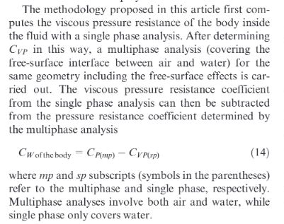
I also wanted know, I have seen research paper.. To calculate wave resistance.. They first calculate resistance in multiphase(air +water), than they calculate resistance in single phase(water), than they subtract resistance calculated from multiphase from single phase, thus they get wave resistance.
I want know how simulate single phase, is it that for single phase simulation we need make air zero with patch under multiphase model?
Please can you clear out, how simulate single phase and from where?
Thanks Rob
February 15, 2022 at 4:11 amtumulpurwar
SubscriberDear Rob
I am using Professional license 2019 R2 Ansys, i am not using student version, Are cell count have limit in professional license too?
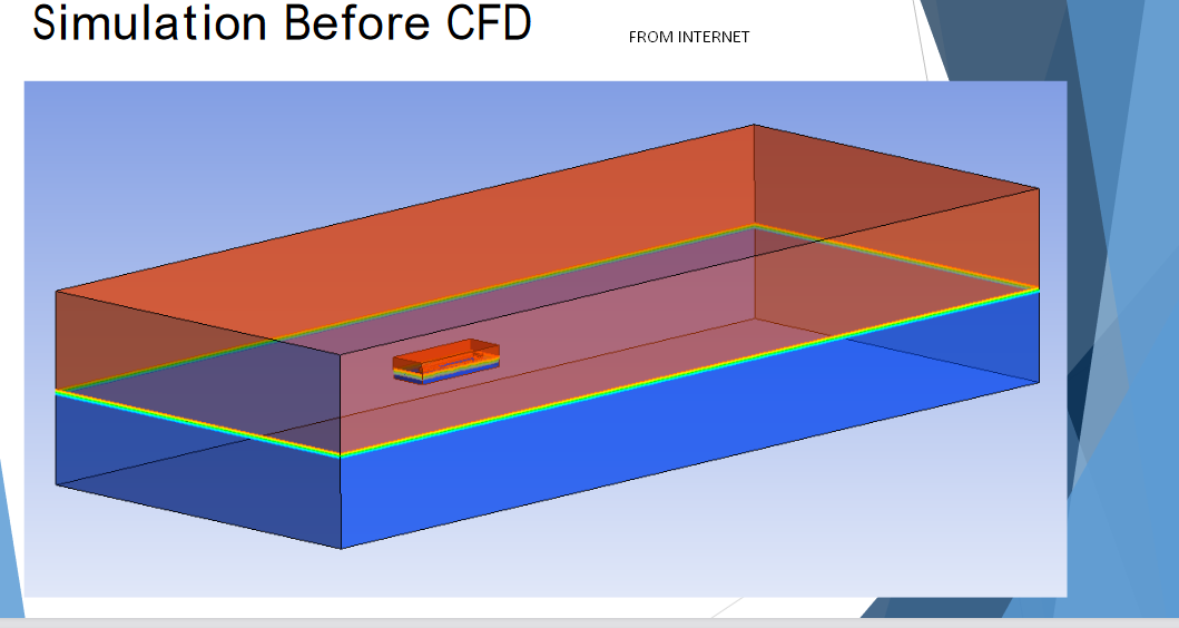
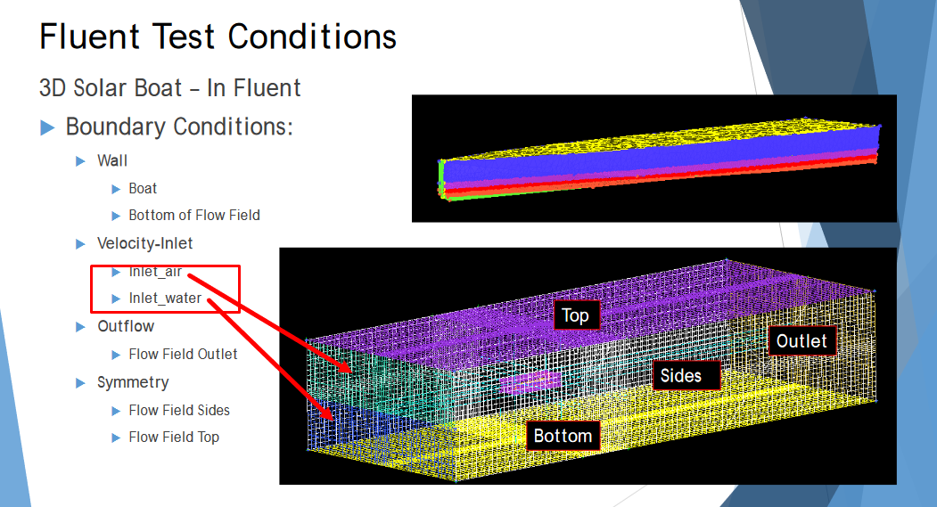
I also want know in image below of one of the CFD of Ship through Fluent, why here they trying use Two velocity Inlet in multiphase vof model?and whats difference if i use only one inlet instead of two inlets..Can you explain?
Thanks
February 15, 2022 at 6:03 amFebruary 15, 2022 at 10:43 amRob
Forum ModeratorThe first slide looks to be an older mesh, it's structured and uses a black background. Only ICEM CFD does this by default now, and Fluent's tended to use a white background for many years for use in presentations (saves on printer ink!). Assuming that, we used to use two boundaries prior to getting the open channel conditions several versions ago. It's not a wrong approach, it's just no longer needed.
Your contours are the result of node smoothing. Report with node values off, and I think you'll see a red/blue contour with some rough edges. The latter is because the mesh at the free surface isn't perfectly aligned with the water level (it's tet/poly) and patching only picks up whole cells.
If you're using a commercial licence the limit to runs is hardware, time and parallel (HPC) keys. The latter purely because otherwise you may need to wait a long time for results. Additionally, if you are using commercial software you should have access to the full support system (if you're paying for maintenance) and really want to update as you're missing out on some VOF stability features that'll speed things up.
February 15, 2022 at 11:21 amtumulpurwar
SubscriberHello thank you for clearing out..it makes sense..we are currently not paying for maintenance, we are currently setting up this initial project to run and later if we will need to increase our work in CFD domain, we will surely look for paying maintenance also.
There are 2 doubts more i have:
1)How to get wave resistance in multi phase(vof)(open channel) , do report shows separately viscous and pressure drag values?
One of the research suggested calculating drag in single phase, than in multiphase, than subtract drag of single phase from multiphase to get wave drag/resistance(photo attached below).
My question is how do single phase analysis in fluent? Is it that in multiphase i select only one material , that is water and simulate, i guess?
 2) My ship is stationary standing in water till now in my previous simulations i tried, only i provided inlet velocity (say 2.7 m/s) ..it means only water flowing with speed of 2.7 m/s...Right? Am i correct?
In reality in towing tank, ship should have two degree of freedom,(pitching, and heave), if i want introduce these 2 dof in my ship, do i need to use dynamic meshing? or i would need to use UDF...i guess UDF is more like scripting which use to be in older versions of fluent?
Can you please clear out my confusion...Thanks
February 15, 2022 at 12:57 pmtumulpurwar
SubscriberMay i also know...as i have just copied youtube video...as they were giving velocity to fluid flow not to vessel.....so why not i let fluid velocity at inlet remain zero(0) and should provide velocity to my ship in forward direction only........as it is calm water test, where water remain calm, i believe this should be the right way to simulate ship in calm water with letting it free in pitch and heave...please can you tell, my thinking is correct?
In Star CCM +...........VOF waves are chosen even if there are no waves present, but the calm water is actually
specified as a flat wave.
Do we also have to choose "flat wave" option as we are simulating calm water test..and from where to choose "flat wave" option in fluent?
thanks
February 15, 2022 at 2:19 pmRob
Forum ModeratorIn a towing tank you move the hull, in a flume you fix the hull and move the water. Same goes in CFD, so it's your call which you do. We'd often do both if the waves are at an odd angle.
In single phase we'd chop the top part off the hull and use a symmetry plane as the water surface. You'd then need to figure out what forces to add/subtract to get the "correct" values. Note, waves add to the viscous and pressure forces, they're reported separately.
In Fluent we can do much the same, turn on the open channel & waves then set the wave as none (or something like that) on the boundary.
February 16, 2022 at 8:10 amFebruary 16, 2022 at 1:30 pmRob
Forum ModeratorIn single phase no, and for VOF as the two densities are fixed I don't think it matters.
February 17, 2022 at 3:57 amtumulpurwar
SubscriberHello Rob
I have one query regarding your last post answer
"In single phase we'd chop the top part off the hull and use a symmetry plane as the water surface. You'd then need to figure out what forces to add/subtract to get the "correct" values. Note, waves add to the viscous and pressure forces, they're reported separately."
Question 1)This single phase simulation, i have to do in vof or where?
Question 2)what you mean by "You'd then need to figure out what forces to add/subtract to get the "correct" values"?
Question 3) Note, waves add to the viscous and pressure forces, they're reported separately."...yes this i understand, but in single phase we dont have free surface, so thus we have no waves, so only thing left is friction and viscous resistance...Right? Please can you correct.
Thanks
February 17, 2022 at 1:00 pmRob
Forum ModeratorIn single phase you don't use VOF as it's a multiphase model. You will also only see pressure and viscous effects. And oops, "not reported separately" for the wave effects. They're included in the pressure & viscous force.
If you chop part of the domain down to the free surface you need to remember that you're not including wake effects etc which distort the free surface. As a result you may find the results differ from the tank tests.
February 18, 2022 at 5:05 amtumulpurwar
SubscriberHello Rob
So in single phase, nor we have waves, nor we have wakes....thus single phase totally exclude any any resistance developing due to wave and wave effects(like wake effect on free surface).........and in multiphase, it include all so it will produce total resistance(which include pressure, viscous,frictional and wave resistance).
Am i right?
In single phase, because we dont use vof model, we cant calculate free surface and its effects? Right??
In single phase, do we get waves???
i want know if we dont have waves, how its practicable , our ship moves in water, but we have no waves??
plaese i am confused, can you correct me, what single phase contain, in my understanding, when we already chopped fluid domain from free surface...we wont we having free surface and its effects and also waves...we will only we left with our ship immersed with viscous fluid ??
February 18, 2022 at 10:15 amtumulpurwar
SubscriberDear Rob
Sorry you can i guess ignore my last commented post, as i believe my confusion is sorted out now...just the one thing for single phase i use general solver? Right?
February 18, 2022 at 11:18 amRob
Forum ModeratorIn single phase there are no waves. The two approaches work, and are used to predict hull drag. However you need to understand the benefits, limitations and cost (time and compute power) of the two methods. Doing some of the courses (top of the page) may help here, otherwise you need to discuss this with your project supervisor having read the theory and understood what you need from the models. I can advise on the how, but your supervisor is better placed to explain the why.
February 18, 2022 at 12:15 pmtumulpurwar
SubscriberThankyou Rob, I understood that confusion, bit conceptual it was,the comments which you was giving days back,now they are coming true, about computation resource and time.
I have parallel processor, with license can share maximum 4 cores, and my RAM is 64 GB,i almost getting 30 million cells to simulate this.
My only question left which is very important is about boundary layer Refinement, i am still not able to reach below 600 y+ value, i used fluent meshing to cope up with manual meshing, but i am stucked since 2 weeks , unable to reduce y+ value below 600 globally...you told about Anisotropic refinement, it helped but upto 600 y+value globally along overall length of ship.
Under Adapt tab, we see Refinement/Adaptation for y+...why we are not using Y+ adaptation, by you chosen anisotropic adaptation?Whats reason behind?
Can you tell how use split ratio in simple way..or any other adaptation tool if you can suggest to get optimal Y+ value.
Thankyou
February 18, 2022 at 12:23 pmtumulpurwar
SubscriberDear Rob
May i lastly know about problem i am facing of not able to get optimal y+ value...my Y+ remain up to 600 globally...Except anisotropic adaptation, are there any other adaptation i can use to refine boundary layers?
i see we have Y+ adaptation, i dont know why you suggested Anisotropic adaptation over other adaptation ...whats reason?
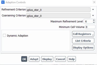
I also dont know..in my 2019 R3 Ansys Version Adapt Tab, i dont get option "Mark"...will it create some problem?(photo below)
And also, do 2019 R3 contains gradient adaptation tool, i dont see in my version
Thanks
February 18, 2022 at 5:30 pmRob
Forum ModeratorMark means to create a cell register and then retain it for use in the solver but not using it to adapt cells. The panels have changed over the last few versions so the term may not be as clear as it once was. You'll find gradient terms in the cell register creation. Basically you mark cells that are then saved in a register. You then adapt the register, or use it for patching etc.
30M cells really ought to be running on 30-60 cores, ideally around 90. Hence my comments about accepting the limitations of the hardware and explaining your approach with what you'd like to have done as a separate section.
Anisotropic adaption splits the near wall cell (usually near wall) in half parallel to the wall. So it's good for increasing the near wall resolution and reducing y+ However, it also tends to need to refine the whole cell layer. "Normal" adaption splits the cells into 8 (hex), 5 (tets) and something (poly) so may be more efficient if used locally.
February 19, 2022 at 8:06 amtumulpurwar
SubscriberThankyou Rob for all the answers, is it possible under 4 cores license with 64 Gb RAM, will it possible to get results if i run it for 1 week? off course ideally 90 cores suit for my project.
Thanks
February 21, 2022 at 6:50 amtumulpurwar
SubscriberDear Rob
For my situation as viscous model will take too many cells(refinement), if i would like simulate just pressure drag, under potential theory approach(that means fluid is not viscous, and have no rotation)...is it possible, that we can do potential theory based simulation as how it is done in other BEM based software in market to just calculate wave resistance without including viscosity and thus no more viscous turbulence model and thus no y+ issue?
Please let me know
February 21, 2022 at 11:16 amRob
Forum ModeratorI'd run with a coarser mesh and explain the reasons for doing so. Running inviscid changes the problem, and given water is fairly viscous will mean the result isn't going to be any better, and more critically can't be defended.
February 21, 2022 at 11:57 amtumulpurwar
SubscriberDear Rob
what you say that i understand...but in Naval field still companies for quick results depends over potential based solver to produce Wave resistance.
I have used in past potential based solver in University , there we can also show wave elevation along the length of hull........so if by chance i want use Inviscid model, than still i can use Multiphase??
Can you also tell for external flow simulation, like of my case with big fluid domain (500 meter X 80 meter X 180 meter), what will be minimum mesh size value in general??...if i put 50 mm for volume target mesh...will it be too small?
As i am getting 33 million overall cells in my fluid domain, which i doubt is too much, because i used, i think very small size(like 20 mm)..Can you please confirm? is it too small?
Also like in software like fine Marine, we can have grid based refinement, which use to be easy in case of mesh convergence study.....here in fluent to do mesh convergence, which mesh size should i make finer every time??I guess i should refine BOI(Body of Influence area), which is covering hull and free surface?Please can you tell.
And if you can also tell what is this warning telling about..i cant get it

February 21, 2022 at 1:08 pmtumulpurwar
SubscriberDear Rob
I have read somewhere in Ansys community..that " the boat will have to be assigned as a rigid and it should be surrounded by a sphere or a box that will deform,"
Is it so?...because i alway leave this ship without defining it with any rigid sort of special mesh...as you also told in old comment, we dont need do anything with boat hull...its in itself fixed...is it so? ..thanks
February 22, 2022 at 7:58 amtumulpurwar
SubscriberCan you please answer above queries ,please Rob thanks
We have already mailed Ansys team in our region today to enquire about license with more cores.
February 22, 2022 at 2:24 pmRob
Forum ModeratorInviscid and multiphase will probably work, but I'm not going to vouch for how useful the results will be. As I've said several times, you need more hardware (and licences - which you're looking at), more time or to reduce the mesh resolution and accept a less accurate answer. Most of the marine companies that I work with (my main role is support - this is only part of my work) use larger clusters for this type of simulation.
The Fluent Meshing messages are suggesting there's a gap in the model somewhere, which has been dealt with and that given the domain/model size some ease of use housekeeping (splitting surfaces by angle to make boundary assignment easier) hasn't been done. One requirement for using Fluent Meshing well is to assign Named Selections in the geometry tool, this then creates the surface labels in Fluent Meshing.
February 23, 2022 at 6:08 amtumulpurwar
SubscriberThanks Rob for keeping up with me with various doubts throughout simulation..we will wait for company to finalize about new license, probably we will go for HPC, as it can integrate in to existing Ansys license to boost speed.
Hope once we fix the license..if there comes any doubt, i will come in this same post back to you.
Good day!
February 23, 2022 at 11:42 amRob
Forum ModeratorYou're welcome. Note, if you're a commercial user and are on TECS you can get direct assistance from either Ansys or the local Channel Partner. We're able to offer a more complete level of support there as the answers are no longer considered public domain. On here we have to be careful to not break the various export rules and laws that we (Ansys staff) must adhere to.
Viewing 76 reply threads- The topic ‘Ansys vof(volume of fluid)’ is closed to new replies.
Innovation SpaceTrending discussionsTop Contributors-
4858
-
1587
-
1386
-
1242
-
1021
Top Rated Tags© 2026 Copyright ANSYS, Inc. All rights reserved.
Ansys does not support the usage of unauthorized Ansys software. Please visit www.ansys.com to obtain an official distribution.
-
The Ansys Learning Forum is a public forum. You are prohibited from providing (i) information that is confidential to You, your employer, or any third party, (ii) Personal Data or individually identifiable health information, (iii) any information that is U.S. Government Classified, Controlled Unclassified Information, International Traffic in Arms Regulators (ITAR) or Export Administration Regulators (EAR) controlled or otherwise have been determined by the United States Government or by a foreign government to require protection against unauthorized disclosure for reasons of national security, or (iv) topics or information restricted by the People's Republic of China data protection and privacy laws.

