-
-
January 8, 2022 at 11:20 am
viv_vid
SubscriberSo I would firstly just go through my project which is about studying microalgae in Mars like environment, so we have created a basic model of a glass tank inside which normal water is there along with the algae. Now at the base of the tank there is a small heating plate which will generate heat in order to maintain the temperature of the water between 20-25 degrees.
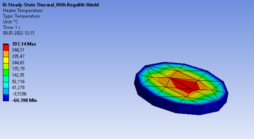
So for this purpose I have been trying to simulate the model by inserting 'heat flow' or 'internal heat generation' but I am not getting a proper result. And I am not sure if this is the currect way to proceed with. For example I tried inserting heat flow directly assigning it to the heater, but unless I apply a heat load of 300000W I am getting the average temperature of water to be 397 degrees (but with the max being degrees, and minimum being -60 degrees). Which clearly doesnt make sense.
January 8, 2022 at 3:28 pmpeteroznewman
SubscriberPlease show all the thermal boundary conditions.
Does the side of the glass tank and the top surface of the water have a convection boundary condition?
Does the large grey base plate also have convection on the top?
Is the bottom surface of the large grey base plate insulated (no boundary condition)?
In Workbench, use File, Archive to save a .wbpz file. Please attach that to your reply and say what version of ANSYS you are using.
January 9, 2022 at 12:19 amviv_vid
Subscriber
Thankyou for your reply Peter. The above mentioned snaps were just a part of the model. I would like to explain you the entire setup first so that you can have a clear image of what I intend on doing. So in my model
1 . So firstly there is an outer dome shaped structure which is the Sun. I have assigned that material to be copper. And this structure is radiating in the heat to the reactor. The temperature of this dome I calculated using steffan boltzman law, as I knew the solar radiation on mars and the cross section area of this dome, So with that I could calculate the temperature of the sun dome.
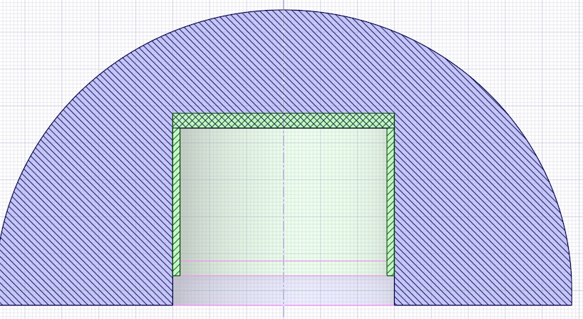
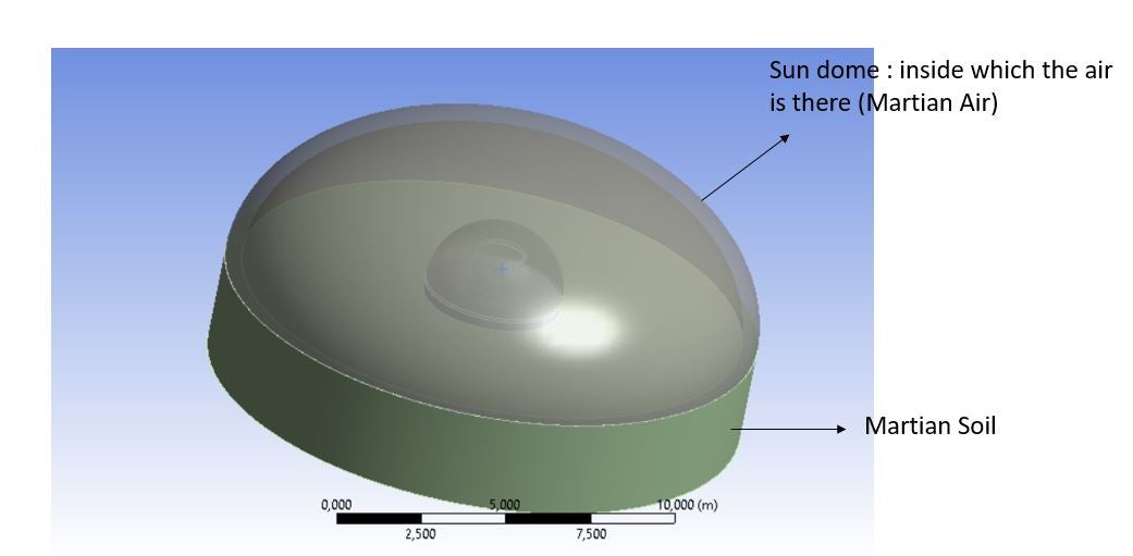 2 . Now the reactor is also dome shaped as shown below. The material of the reactor shield is made of martian soil (regolith). Inside the regolith shield is Martian r and then the glass tank with water and heater as mentioned in my question. I have also attached my archived file here. Whenever you have time please only look into the steady state thermal of the reactor with regolith shield only. As I have started with that. The transient one is yet to be solved but I decided to proceed to that once I have a clarity with the steady state. So my goal in the end is to make the water temperature between 20-25 degrees, and to do that what amount of heating power would be required. That is the main task of my project. It would mean a lot if you could guide me through this and let me know where my errors are if there are any. I am not an expert in Ansys and I could not find any help from others hence I decided to post this and ask directly to the experts.
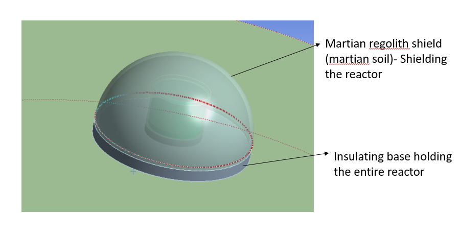 Thankyou once again for taking out time for this. It really means a lot! I understand it is kinda difficult to explain all of this over chat, so is it possible to contact you guys virtually via a zoom call or so where I can explain you my concern in a much organized way?
January 9, 2022 at 12:20 amviv_vid
SubscriberThankyou Peter for your reply. I would firstly like to explain you my model so that you have a clear understanding :
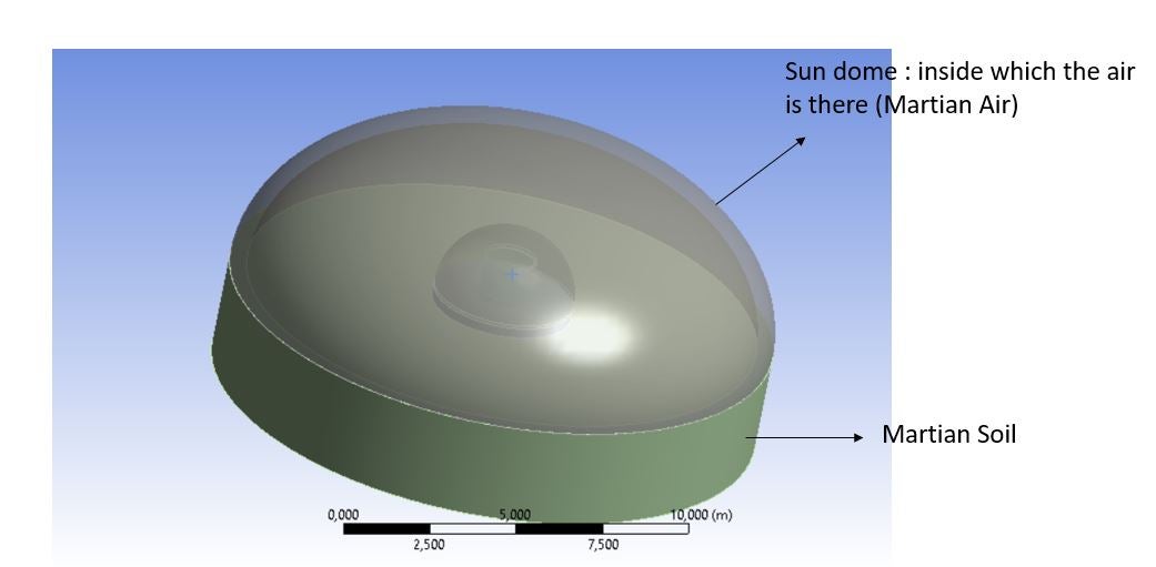
There is a dome shaped structure as shown in the figure. This is the Sun as I wanted to assign solar radiation to the reactor. Now the material selected is copper and the temperature of the dome I found out using stefan boltzman law. Inside the Sun dome is the Martian Air.
 Now as shown below is the reactor model with again a dome protecting it. This dome is made of Martian Soil (regolith). Inside which there is the Martian Air, Glass tank and the heater as mentioned in my previous question.
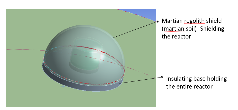
I am also attaching the archived file of my project here. Whenever you have time kindly go through the 'steady state version with regolith shield'. I have yet not moved to transient one as I wanted to get a clarity of this first.
So my primary goal is to maintain the water temperature between 20-25 degrees and to do that what amount of power would I be needing. So I am getting some wierd results while running this and something doesnt make sense. It would mean a lot to me if you could shed some light on this as I am a beginner to Ansys and I could not find help anywhere else. Hence I decided to ask the experts itself. Also I am using Ansys 2021 R2 version.
Thankyou so much again, it really means a lot. To explain all of this is kinda tough over comments, is there any possibility of contacting you via some zoom call so that I can explain it to you in a better way?
January 9, 2022 at 1:56 pmpeteroznewman
SubscriberDear Vivek You have done a good job explaining your project and I can see the details in the project file.
One mistake I found in Geometry A is that the Heater solid overlaps with the Liquid Column solid. None of the solids should overlap, nor should there be any gaps. While you are fixing that problem, the diameter of the heater is slightly less than the water. This will leave a thin ring of water around the heater. It would be cleaner if the heater is the same diameter as the water.
The model uses contact to connect adjacent solids. This is permitted, but I recommend you try the other approach, which is to use Shared Topology. That means to use SpaceClaim to put all the solids into a single component, then on the Workbench tab, click the Share button. Now every face that touches another will have nodes on the coincident face shared between the two volumes, and that is how heat can be transferred through the media. After you have done that, delete all the contacts under the Connections folder in Mechanical.
In Mechanical, while meshing, add mesh controls to put smaller elements where you expect high temperature gradients. One way to do that is to put a coordinate system origin at the center of the region where the high temperature gradient is expected. Apply a Body Sizing mesh control to the solid of Type: Sphere of Influence. Select the coordinate system for the Sphere Center and Radius where the specified Element Size will be applied. The mesher will gradually grow the element size to the setting for the rest of that body, or the global size. The combination of Shared Topology and smaller elements will help with the accuracy of the simulation results, however, the model size will increase.
My comments above are based on my expert knowledge, which is in Structural analysis. My comments below are based on my general knowledge. I am not an expert in thermal analysis and haven't done any models with radiation loads, though I have read some tutorials on this topic. The Radiation loads on the two domes have the same Enclosure number of 1 and Type is Open. I think that means that radiative heat can escape the system out the annular gap between the domes. But the Martian Soil surface closes off this annular gap between the domes, so a correction to the model would be to change the Enclosure to Closed and include the Martian Soil surface.
I have built very few CFD models so I am not expert in this field. I did one relevant model, the convective cooling of a hot pipe using CFD: /forum/discussion/8778/convection-question Some comments in that discussion apply to your model. When there is air and gravity, hot air rises and cold air descends. This movement of air carries heat. The structural solver used in Steady State and Transient Thermal analysis models convective heat transfer based on experiments that provide a Film Coefficient, but these experiments have an unlimited supply of ambient air at one temperature. Convection from the outer surface of the Regolith Shield to the Martian atmosphere has the unlimited supply of ambient gas that is needed to make this a meaningful load. Once you add a dome to seal a specific volume of air, there is no longer an unlimited supply of constant ambient temperature for the Convection load. Note that air is a good insulator when it cannot move. The structural solver can only conduct heat through the air volume. You need a CFD solver to get the convective heat transfer through the air in the fully enclosed dome.
The same comments apply to the water in the tank. Convective fluid movement will carry heat from the fluid at the heater up into the fluid above. Conduction will also transfer heat from the fluid at the heater to the fluid above. Water is 25 times more conductive than air, and the gravity on Mars is 0.38 times Earth gravity, so you might find that the convective heat transfer in water is small enough to ignore and then you don't need a CFD model for the water so you can just have conduction, but build a small CFD model to calculate both then decide.
Check your material data, this site http://hyperphysics.phy-astr.gsu.edu/hbase/Tables/thrcn.html gives the conductivity of water and air. In your model, the air is about right but Water is 1e+15 W/m/C while the correct value is 0.6 W/m/C. Having a value that is off by a thousand trillion could give some weird results.
Regards Peter
January 9, 2022 at 11:24 pmviv_vid
SubscriberThankyou so much for your efficient and fast reply Peter!! That is a whole lot of insight and means a lot really! I will look into all those comments and implement them in my model and get back to you in a week or so with the corrected one. Hope you will have time to assess it.
I just have a question regarding the CFD modelling that you suggested in order to get convective heat transfer of air inside the regolith shield. I dont know any CFD solver, I was willing to learn FLUENT, but I dont know if I have enough time left to learn it and use it here. Is there any other alternative that I can use here itself? Also if suppose I get time to learn CFD, would you be recommending FLUENT for it? And for the convective heat transfer of water, since it wont make any difference, I can just go ahead with adding conduction to it right?
Again Thankyou for taking out time to go through everything, I will get back to you once I correcting it, also will ask you if I encounter any problem in between.
Vivek
January 10, 2022 at 1:46 ampeteroznewman
SubscriberI only know a little bit of FLUENT. There are plenty of tutorials available and experts on this forum to help you.
I suggested you evaluate the contribution of convection vs. conduction in a small CFD model of the water tank to see if you could ignore convection. I didn't say convection won't make a difference for water, only that it will have a lower contribution to the total heat transfer than it does in air.
How much time do you have left on this project?
Peter
January 11, 2022 at 2:56 pmviv_vid
SubscriberOkay I will do a bit research on the tutorials available. I still have 3-4 months left for the project, so maybe I can apply compare contribution of convection and conduction.
Btw while adding background conditions, I found convection, radiation,heat flow, internal heat generation etc, but not conduction in that section. How can I add conduction between two bodies?
January 11, 2022 at 6:49 pmpeteroznewman
SubscriberConductivity is a material property of the body, not a boundary condition. It is the external faces of the body that can have a boundary condition. If no boundary condition is applied to an external face, it is automatically an insulated face (heat flow = 0). If you use shared topology between solids, after meshing, the coincident faces between solids is no longer considered an external face. Each body has its own conductivity and heat flows across the coincident shared internal faces. If two bodies have a contact defined between them instead of shared topology, the contact by default will have perfect thermal conductivity (zero resistivity), but you can optionally add some thermal resistivity to heat flow at the contact surface.
January 12, 2022 at 3:16 pmpeteroznewman
SubscriberHere is a CFD example of convective cooling of a hot pipe with an unlimited supply of cool air.
The last post has a link to four YouTube videos of a complete CFD tutorial for this problem.
/forum/discussion/comment/143821#Comment_143821
January 14, 2022 at 9:26 pmviv_vid
SubscriberThankyou so much for your prompt reply Peter. I will look into the link and the videos you refered to for CFD Tutorial. Meanwhile I have tried implementing the corrections and I rectified the overlapping water+heater bodies and separted them. Also made the heater radius same as the inner glass tank radius. I also did the shared topology thing you talked about. Now while meshing, I selected heater as the body and made its centre as the new coordinate system and then applied sphere of influence over it with a radius of 4 metres as shown in the figure
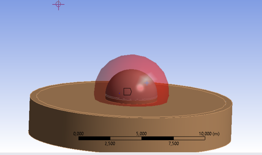 Now I wanted to know will this mesh all the area highlighted within that sphere of influence and then onwards the meshing size will reduce while moving farther away from the sphere. Is that right? Because then I dont need to individually specify an element size for each element, for example be it the regolith shield, as it is already within the sphere, I dont need to insert body sizing by selecting the material as regolith shield (with a different element size maybe). Could you clear this confusion?
January 14, 2022 at 11:40 pmpeteroznewman
SubscriberYou select the bodies you want to be affected by the Sphere of Influence. If you select All Bodies, then any body that touches the sphere will have the smaller element size inside the sphere, and the element size will grow to the global default element size specified under the Mesh branch of the outline. You can also put a sphere of influence inside a sphere of influence if you need to.
January 16, 2022 at 3:09 pmviv_vid
SubscriberOkay, So now I have added the sphere of influence mesh for
PBR Base
Inside Air
Outside Air
Martian Soil
And then for the rest bodies I have selected the mesh as Body sizing : element size. Now while running the mesh I am getting the following error.
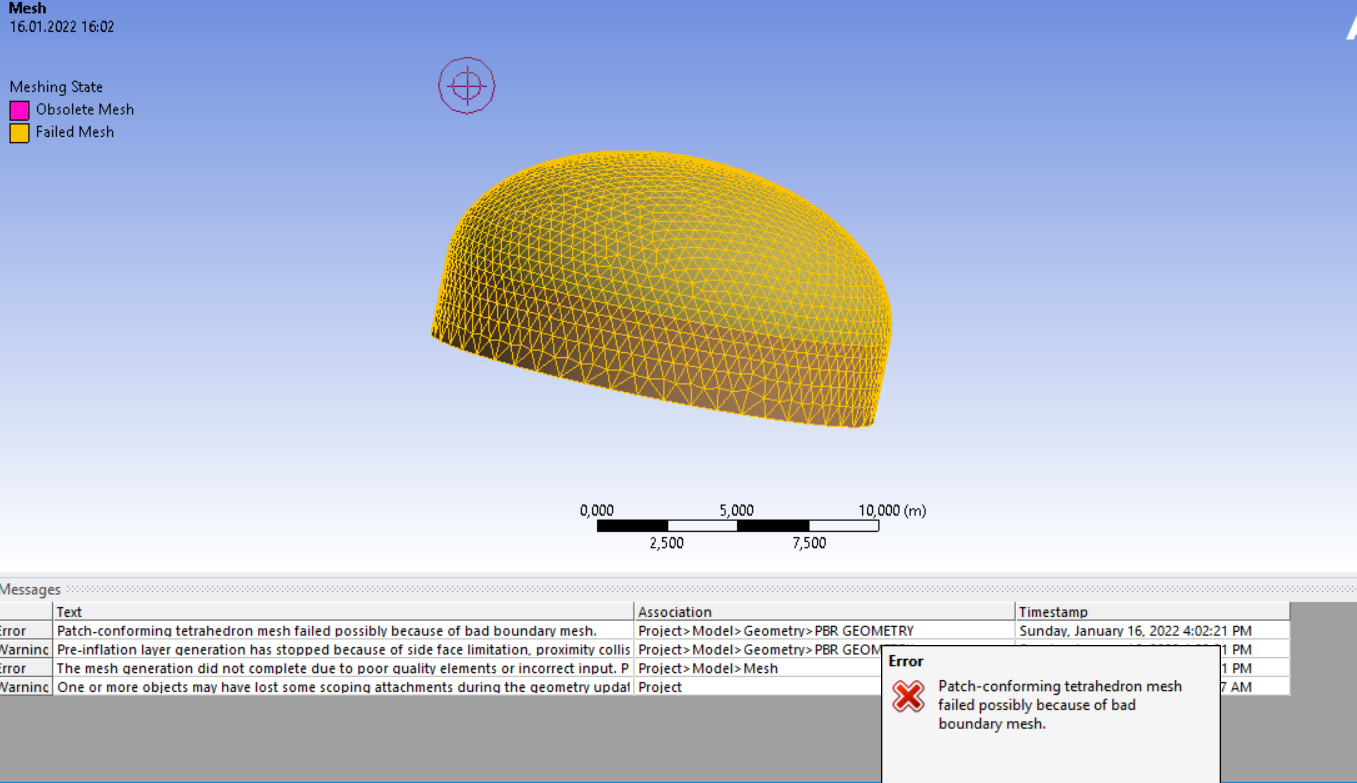 So I suppressed the patch conforming tetrahedron mesh method and then tried generating the mesh again, but again I am getting an error stating : A mesh could not be generated using the current meshing options and settings.
Could you help me with this, I am also sending you the attached archived file.
January 16, 2022 at 11:28 pmpeteroznewman
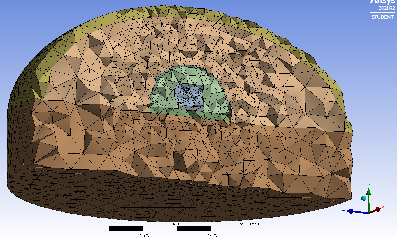
SubscriberYou can mesh system B if you hide all the outer parts so you can see the heater. Click on the Mesh branch of the outline then right click on the heater body and Mesh Selected Part. Now unhide the water, Mesh Selected Part. Keep showing the next layer of the onion. In this way you will get a successful mesh.
 January 18, 2022 at 11:16 am
viv_vid
SubscriberThankyou for that suggestion regarding the meshing Peter, It worked perfectly. For now I am deciding to run the simulations without doing the CFD analysis to just check the output, but I have few questions while inserting the boundary conditions :
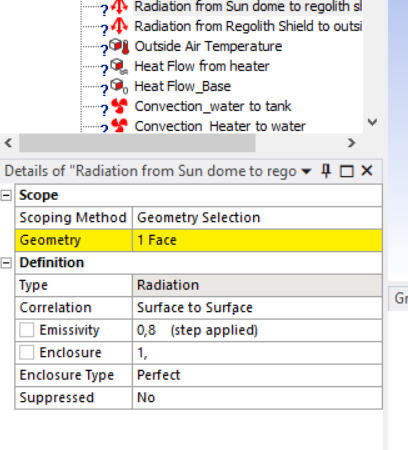
As you told me earlier regarding the radiation, I changed the enclosure type from open to perfect. But now I see a '?' sign on all the three radiation conditions on the branch tree. I dont understand why.
While inserting the convection towards the inner part of the regolith shield, that is from the inner face of the regolith shield to the air inside, the ansys asks me to input an ambient temperature. That means I have to input the Air temperature which is inside right? But that temperature I cannot feed in since I do not know what temperature it will be inside the regolith shield, as that is the result I wanna obtain eventually. Similarly for the case inside the water tank for convection between the tank and water. Can you suggest me how should I proceed with it?
I am sending you the updated file
Thankyou Vivek
January 18, 2022 at 12:32 pmpeteroznewman
SubscriberI'm not an expert at Radiation loads so you should reply with images that explain each radiation load in detail and hope you get an expert reply.
As far as I know, Mechanical can only simulate a convection boundary condition with a constant temperature of ambient air. That is not true for an enclosed air volume that is going to heat up to an unknown temperature at steady state. This is why you need to have a CFD model which carries the heat from one place to another while converging on the steady state.
January 18, 2022 at 3:42 pmJanuary 18, 2022 at 4:35 pmpeteroznewman
SubscriberHave you taken this free course? /courses/index.php/courses/radiation-between-surfaces/
January 18, 2022 at 7:39 pmviv_vid
SubscriberYes I have seen this, and In the first file which I have sent you, in that too I have used the same radiation method with correlation-surface to surface, but at that time I did not get this '?' sign as you can see in the below image :
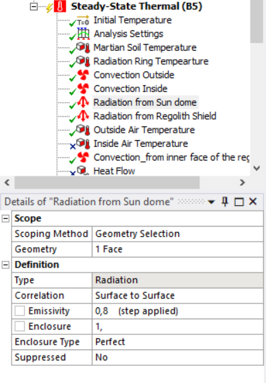 But now in the new file where I have rectified the geometry and also the meshing, in that model I am finding the '?' sign. Does it have to do anything with the change in geometry or meshing which I did?
January 18, 2022 at 11:36 pmpeteroznewman
SubscriberTry closing Mechanical, opening the geometry in SpaceClaim and on the Workbench tab, click the Unshare button, then open Mechanical again. See if that allows you to define Radiation.
January 19, 2022 at 10:58 amviv_vid
SubscriberYes That did solve the Issue, Thankyou Peter. But then that means I cannot use share topology anymore? is there any alternative to this?
January 19, 2022 at 11:16 amviv_vid
SubscriberI tried unsharing just the sundome and kept the rest of the materials as shared, and it worked too but for only the radiation from sun dome. Now for radiation back from the Martian soil and Regolith shield cannot be done as it is sharing the topology with other materials. Unsharing it wont make sense as it is in contact with the outside air.
January 19, 2022 at 11:50 amviv_vid
SubscriberI also tried just unsharing the topology for the sun dome, and kept shared topology for rest of the bodies, and that worked too, but only for the radiation coming out from the Sun dome. Now for the regolith shield and Martian soil, I cannot do the same since it is sharing topology with other bodies. For Sun dome I can keep it unshared, as there is only radiation coming out..but for the martian soil and regolith shield as it is in contact with the outer Air, convection is also playing a role, hence cannot unshare those bodies.
January 19, 2022 at 1:04 pmpeteroznewman
SubscriberBonded contact can be automatically created at all the coincident faces and will be used to transfer heat between bodies. I don't work with Radiation loads so I didn't know Shared Topology prevents applying those loads.
February 7, 2022 at 11:46 amviv_vid
SubscriberHello Peter I saw your tutorials on CFD using Ansys Fluent, and also some other online course videos related to FLuent, so I decided to work on the same project using Ansys Fluent. I linked the same geometry to fluent and then ran the mesh individually for each elements just like I did with ansys structural. but then when I click on update I am getting the following error. Could you help me rectify this?
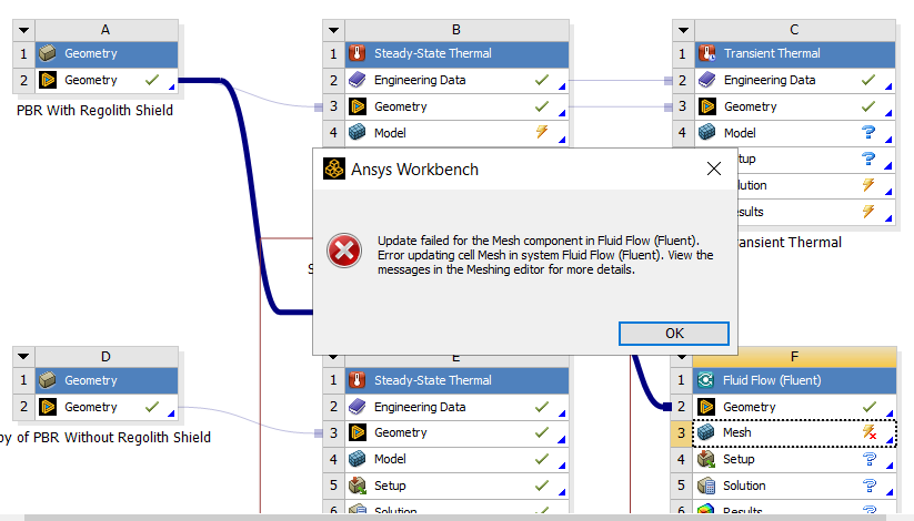 I am also attaching the archived file here. Thankyou
February 7, 2022 at 9:49 pmviv_vid
SubscriberHope you see this :)
February 9, 2022 at 9:04 pmpeteroznewman
SubscriberSorry for the delay in replying. It was a busy few days at work and I only spend time here when I am have spare time.
If you open the Mesh row, clear generated data and Generate Mesh, you get this error:
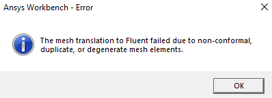 The problem is the heater and the water solid bodies overlap. That is not permitted.
Another problem is the Glass Tank overlaps with the Inside Air.
February 10, 2022 at 2:09 pmviv_vid
SubscriberThankyou for your reply peter, I really appreciate your efforts sincerely. I tried fixing the overlapping between the heater and the water. But I could not find the overlapping between the glass tank and the inside air. I tried checking by clicking the intereference button on the prepare tab, It showed there are no interferences. Is there any other method to check where my bodies are overlapping?
Before jumping into fluent, I tried running my simulations in Transient thermal. But strangely I ran the simulations for 100 steps which took around 4 hours to solve, but the results did not make any sense. These are my doubts regarding transient thermal :
1.I imagined the water temperature might reduce from -60 degrees to atleast a -58 degrees or so, but it hardly changed. Should I run it for more steps, like 1000 or maybe 10,000? but then the problem is its gonna take days to solve, Is there any way to reduce this duration? One step accounts to 1 second right?
2.also running for more time steps is taking up a lot of pc space, hence I am not able to save the file in the end as an error message prompts up 'there is not enough space' or 'the file could not be saved'.
3. Also when I started running the solution a message prompted up mentioning 'the initial increment may be too large for this problem', although I was able to run the simulations.
I am attaching the updated file here for you to have a look at both the overlapping bodies and the transient problem
I hope you can clear my doubts. Thankyou Vivek
February 10, 2022 at 6:59 pmFebruary 11, 2022 at 1:04 amviv_vid
SubscriberOkay Thankyou, so I can move ahead with the current model right as there is no interference? Also Could you help me clear my transient problem doubts whenever you get time, Thankyou!
February 12, 2022 at 10:57 ampeteroznewman
SubscriberUse an axisymmetric model to reduce the compute time by an order of magnitude or more.
February 12, 2022 at 11:34 amviv_vid
SubscriberI thought of doing that. For that I will have to create the entire geometry first in 2d right? and then mention in the geometry section 'axisymmetric'. is there any other method where I can convert the present geometry itself to axisummetric? If not I can create the model again in 2d and run the simulation, but then can I assign the boundary conditions in 2d as well the same way I did for 3d?
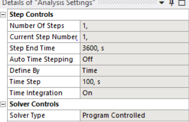
I also came up with a solution while looking up in the internet by increasing the time steps...so I ran the simulations for example 10000 seconds with a step size of 100, and the computing time was reduced. I understand the efficiency of the output will be reduced here, but I think for my project where there isnt much change in the temperature over seconds, I can consider this method of increasing the step size to 100 right?
something like this where I ran the simulation for 1 hour=3600 secs with a step size of 100.
February 12, 2022 at 3:08 pmpeteroznewman
SubscriberTo get a 2D model, open the geometry in SpaceClaim. Use the Move tool to move all the solids/components so that the axis of symmetry lies along the Y axis. Create two planes: XY and YZ. Use Split Body to cut all solids with the two planes. Hide or delete 3/4 of the pieces, leaving 1/4 that have a face in the +XY plane. Select all faces in the +XY plane, type Ctrl-C, Ctrl-V and you will have all the surfaces you need to make the 2D model. Delete all the solids. Go to the Workbench tab and click the Share button.
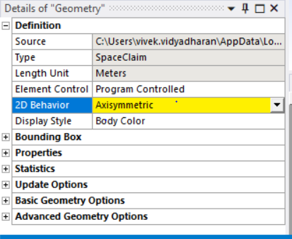
In Workbench, create a new Transient Thermal model. Don't try to reuse the 3D model you have. On the Geometry cell, open the Properties panel and on the Analysis Type, set it to 2D.
In Mechanical, click on Geometry and set the 2D type to Axisymmetric, then apply all your BCs.
Regarding Time Stepping, have you tried setting Auto Time Stepping to On? That way you allow the solver to choose whether it needs a small time step and allow it to use a large time step. That will save some wait time for either a 3D or 2D model to finish the computation.
February 13, 2022 at 11:32 amFebruary 13, 2022 at 12:48 pmpeteroznewman
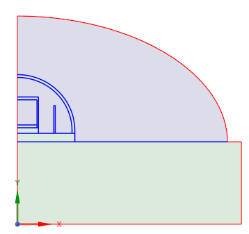
SubscriberThis instructions were to select the faces on the +X side of the XY plane. You have faces on the -X side of the XY plane. Nodes are not permitted to have negative X values.
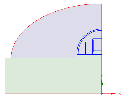 Rotate the surfaces by 180 degrees about the Y axis. Note that you had one surface hidden, and that must be shown and transformed or you will still get a yellow field. Once you get all the geometry on the +X side, the Axisymmetric field will be allowed.
 February 15, 2022 at 11:19 amFebruary 15, 2022 at 8:44 pm
viv_vid
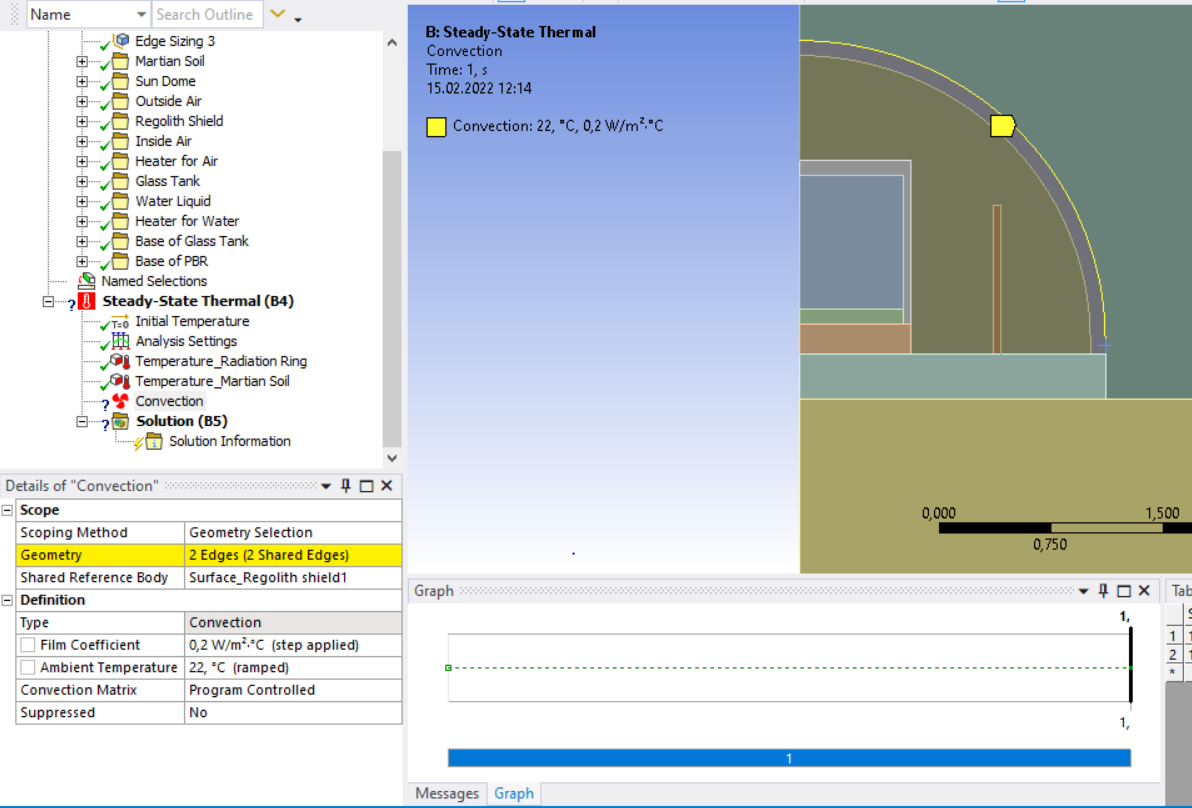
SubscriberI read in the Ansys manual that for 2D objects it is not possible to give convection over edges, as convection can be only given to faces..is that right? if yes then how can I resolve this issue and add convection here?
February 16, 2022 at 10:14 pmpeteroznewman
SubscriberIn an Axisymmetric Model, an edge represents a 3D face and you can pick an edge to define a convective BC in an Axisymmetric model. Note that is has to be a Boundary edge, not an interior edge.
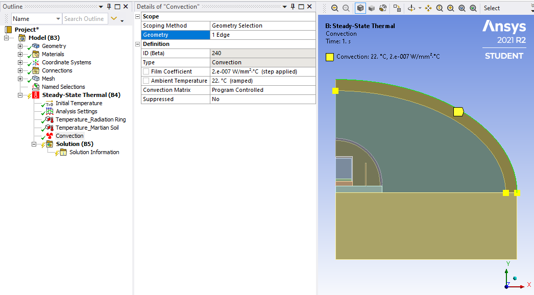 The issue you have is trying to apply a convective BC to an interior edge (representing a 3D surface). That is not allowed. If you suppress the Sun Dome and the Outside Air, you can apply the Convection to that edge you selected.
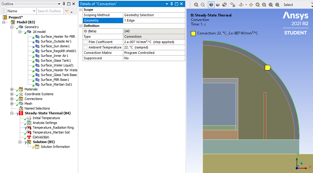 We had this discussion before on the 3D model, you can't apply a convection BC to an interior surface. You need the outside air to be modelled using a CFD solution for it to convect heat through the outside air.
March 4, 2022 at 10:41 pmviv_vid
SubscriberHello Peter, So I did a bit of studying to incorporate CFD analyses in my project using Ansys Fluent. I used the 2d structure and used the axysymmetric option. Now in one of the vidoes of Fluent I saw that under the Fluent solver you have to couple your Mesh interfaces, only then the solver will know that there will be a heat transfer between these surfaces. But since in my model I have used Shared topology in spaceclaim, will that be equivalent to the coupled mesh interface? Because once I share the topology, I do not see any contact interfaces in the Mesh interface option.
So I tried unsharing the topology so as to couple the mesh interfaces. but then after unsharing the topology, when I try to open the Fluent solver I am getting this error as shown below
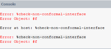 And I am also not able to see my model in the Fluent solver anymore. Now I was not sure whether to ask this question in this section or under the fluent section of ansys, but since you already are up to date about my project, I was hoping you could help me or you could guide me to someone who is an expert in Ansys Fluent. Thankyou for your help. I am also attaching the archived file here
March 6, 2022 at 2:56 ampeteroznewman
SubscriberPost your question in the Fluids category.
I noticed that if you make changes to the geometry, such as using the Share button in SpaceClaim, don't try to update a previous Fluent model, you will often see errors. Instead, start a new Fluent model and read in that same geometry and there should be no errors.
Viewing 39 reply threads- The topic ‘I have a doubt regarding steady state/Transient thermal which I am using currently for my Masters’ is closed to new replies.
Innovation SpaceTrending discussionsTop Contributors-
5159
-
1836
-
1387
-
1249
-
1021
Top Rated Tags© 2026 Copyright ANSYS, Inc. All rights reserved.
Ansys does not support the usage of unauthorized Ansys software. Please visit www.ansys.com to obtain an official distribution.
-
Ansys Assistant will be unavailable on the Learning Forum starting January 30. An upgraded version is coming soon. We apologize for any inconvenience and appreciate your patience. Stay tuned for updates.

