TAGGED: ansys-apdl, element-types, modal-analysis
-
-
January 6, 2022 at 3:02 pm
Richard_317
SubscriberDear all,
I am currently working on my modal analysis of FRP plates. I used Shell281 to model a Graphite-Epoxy composite plate under SSSS boundary condition and the result I got is close to my validation results. However, when I used Solid185 to model the same plate, the results obtained are no longer agreed with the one obtained using Shell281. I have set the layer construction to layered solid and I have defined the fibre orientation using the shell sections. So I am wondering is it the problem is due to my setting?
When using Shell281, the SSSS B.C. were set by setting the 4 edges to have zero displacements in z-direction (upward direction) and the rotation normal to the edge was also set to zero (i.e. ROTX = 0 when x=0 and x=a & ROTY = 0 when y=0 and y=b).
While for Solid185, I set all edges to have zero displacements in the y-direction (upward direction) and zero displacements for the DOF parallel to the edge (i.e UX=0 when z=0 and z=b & UZ=0 when x=0 and x=a). i had modelled it as a solid and divided the thickness into the required number of layers when meshing.
January 6, 2022 at 4:28 pmErKo
Ansys EmployeeHi
I think in theory it should be possible to get similar results (of course we can not guarantee for all cases). Below is an example of two isotropic layers for solid185 layered solid (needs command snippets to use that (layered solids) in wb mechanical) and a double layered shell181.
So it is a matter of setting it up correctly I think, which can be perhaps tricky. Related to that (setup: boundary conditions) I have restrained 4 edges (only in the z direction - it is ok if we get 3 rigid body modes) that are in the midplane of the solid 3D part since that is similar to the shell (see last image below). Also I have at least two solid elements through each layer so 2 layers * 2 solid_3d_elements / layer = 4 elements through the thickness in total as seen below.
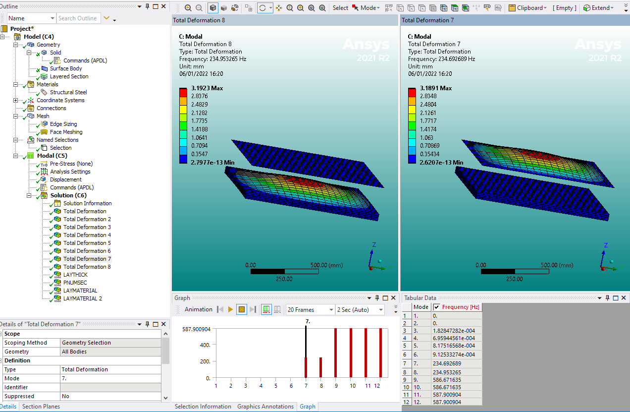
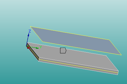
Hope this helps
Erik
January 7, 2022 at 4:52 amRichard_317
SubscriberHi Erik If i want to model using solid185, i should separate the composite plate numbers of volumes according to my desired layers? Or either way also work?
January 7, 2022 at 7:14 amErKo
Ansys EmployeeHi
I used a layered solid185 option - see vm144 in the verification manual on how to use them (needs sectype and secdata).
Of course the other option as you say is to explicitly model each lamina/layer so have one part with one material for each layer, and so on using standard solid185 (this is different to the layered solid185 option, keyopt 8). Modelling them explicitly can be tricky when the layers are thin like in CFRP composites, hence why one can use a layered shell elements for these structures.
I will leave this with you.
Erik
January 7, 2022 at 2:15 pmRichard_317
SubscriberHi
I am actually using ANSYS Mechanical to model it, and I solely use the GUI to do all the setup instead of using the command as I do not know how to use them. So I was wondering does that make any difference?
Here are my setting steps:
1) Preferences was set to "Structural"
2)Preprocessor: Element type is "Solid185" and changed the layer construction to "Layered solid"; Material Props are linear orthotopic (E1= 120 GPa, E2=E3= 7.9 GPa, G= 5.5 GPa, ╬¢= 0.33, ¤ü= 1580 Kg/m3); Shell sections are [(0/90/0/90/0)_s] with a thickness of 0.000269m per ply; Model was created using block volume (x=0.2m length, z=0.2m width, y=0.00269m thickness); Mesh was created by having 10 elements along with the thickness and 20 elements along the length and width.
3)Solution: Modal analysis to obtain the first 20 mode shapes. Loads were defined by applying under structural displacement -> on lines -> all 8 edges were set to have zero displacements in the y-direction (as y-direction is the axis normal to the plate surface). And solve.
When I am using the Shell281 element, the result I got for the first natural frequency is 301 while Solid185 gave me 258. I know somewhere of my setting might be wrong but I really have no idea where did I make a mistake or what I have missed.
January 7, 2022 at 2:23 pmErKo
Ansys EmployeeHi
I can not offer also much more assistance, but
perhaps if you add inline screenshots of all these (point 1 2 and 3) then perhaps some users and members of the forum might be able to help.
Also in point 3 you mention loads, and then you look at natural modes and frequencies in a modal analysis. Loads are not accounted for and can not be used in a modal analysis, also clarify that and you will be more likely to receive some help from users in this forum, because it is a bit confusing at the moment.
Finally I assume you mean Ansys APDL and not ANsys mechanical which is inside Workbench - so you use Ansys MAPDL, just as used in this post (/forum/discussion/34892/some-help-with-constraints-in-apdl-would-be-greatly-appreciated#latest)? Also make sure you restrain the midplane of the solid just as I showed (you would need to nsel all nodes and restrain as needed). Perhaps also try first with a simple model in order to get the set up correct.
All the best of luck
Erik
January 7, 2022 at 2:44 pmRichard_317
SubscriberHi,
Yes, i am using ANsys MAPDL, sorry for the mistake.
Thank you for the response all along, of course, I will keep trying and attach screenshots if I still can't solve it. and I did try with a simple model which I get similar results, that's where I know my boundary conditions were set correctly. Again, really appreciate your response.
January 7, 2022 at 3:48 pmRichard_317
SubscriberHi all,
Here is my setup for my modal analysis of simply supported 10-layer composite plate using Solid185 layered solid element:

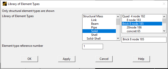
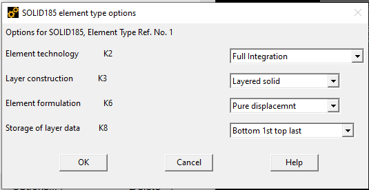
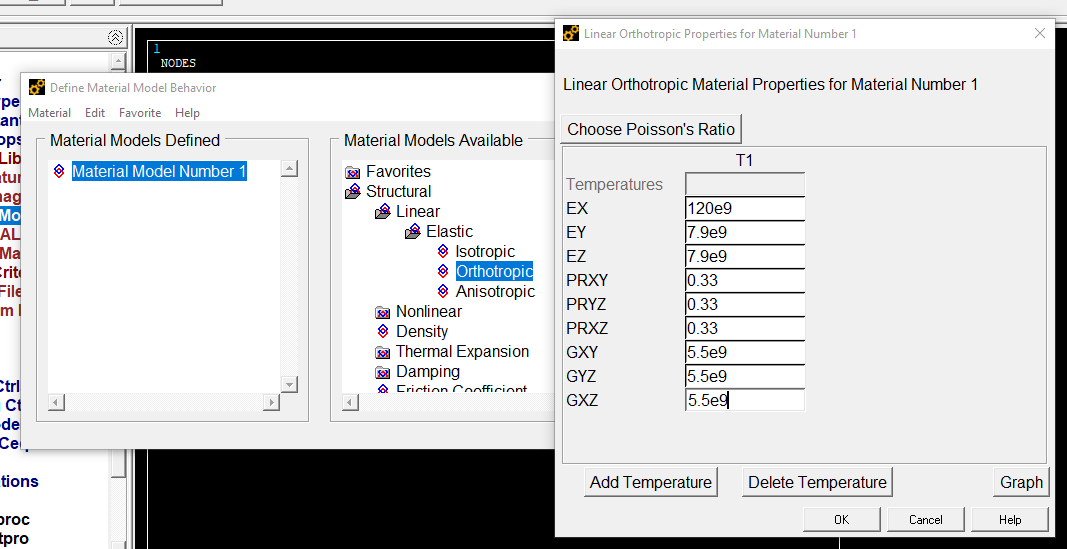
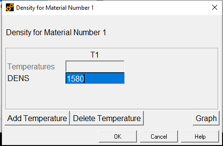 Here is the composite layup of [(0/90/0/90/0)s]:
 Here I am creating the volume of the composite plate by defining the volume:
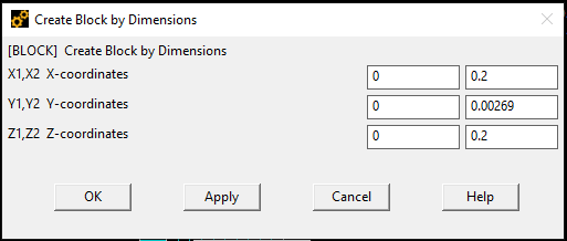
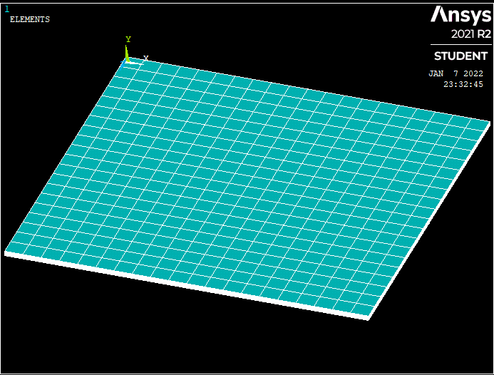
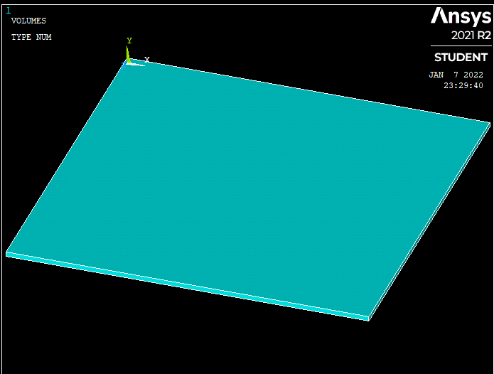 Here is my mesh with 20x20 elements and 10 elements along the thickness to represent the 10 layers:
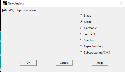
 Setting the analysis type to Modal Analysis:
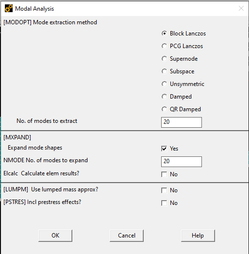
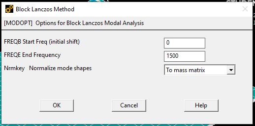
 Obtain the first 20 modes shapes with the constraint of below 1500Hz
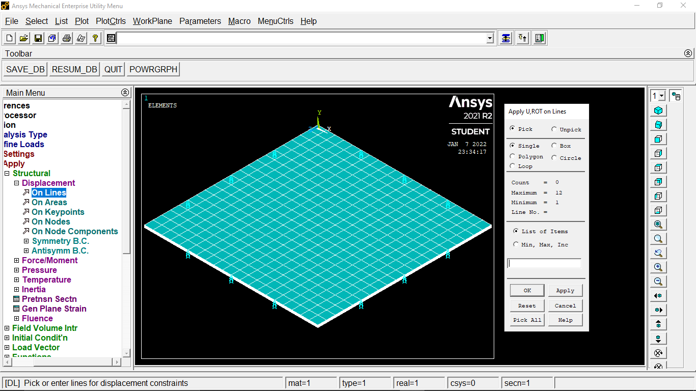
 Since I am studying the natural frequency of this simply supported plate, I set the 8 edges to have UY=0.
 This is the results, the first frequency is 259.95Hz.
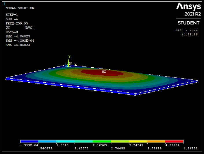 The frequency I am looking for should be around 302Hz, which is what I got by using Shell281 and also from the published results. The reason I want to use Solid185 is because I will use it for modelling delamination composite, since it seems to be not possible to model delamination using Shell281 (correct me if I am wrong, do let me know the ways too if possible).
January 7, 2022 at 4:10 pmErKo
Ansys EmployeeHi
I think the main issue here is that the face normal of the top and bottom faces should be pointing in the Z-direction just as it does below in the example I did (in the image you show they are pointing in the Y direction - so the plate (width x length) should be in the XY plane and the plate normal is Z). This is described a bit in the help manual under solid185 (element reference).
Try that (so width along Y length/long direction along X and thickness direction along Z).
Also as we said can you try to add the BC not on the edge but on the nodes half thickness up from the bottom face so on the midplane so to speak a I did here on the bottom 3D part (try the first above and if this does not resolve try this, but it could make little difference as the plate is very thin):

As for the delamination I think you need to model every lamina/ply explicitly (so every layer is a volume and part) I believe and then disconnect nodes to represent like a crack between plies/laminas in a modal analysis and to see how this changes the modes - perhaps there is some material out there that can help.
All the best
Erik
January 7, 2022 at 4:46 pmRichard_317
SubscriberHi
i have tried restrained the edges' nodes at the middle plane and yet it still provide me the same results which is 259Hz. I will try modelling it in Z direction and see whether there is difference. Once again, thank you for your reply.
January 8, 2022 at 1:47 pmRichard_317
SubscriberHi Erik,
I have tried to model it with the face normal of the top and bottom faces pointing in the Z-direction and it works!!!
Thank you for your time and advice. Very grateful to have you in the community.
January 10, 2022 at 6:54 amErKo
Ansys EmployeeThat is great - I am closing this one incase anyone else will see the same issue.
Should you have any other questions, feel then free to open a new discussion.
Erik
Viewing 11 reply threads- The topic ‘is it possible to get similar results by using Solid185 and Shell281 element types?’ is closed to new replies.
Innovation SpaceTrending discussionsTop Contributors-
4969
-
1645
-
1386
-
1242
-
1021
Top Rated Tags© 2026 Copyright ANSYS, Inc. All rights reserved.
Ansys does not support the usage of unauthorized Ansys software. Please visit www.ansys.com to obtain an official distribution.
-


