-
-
December 21, 2021 at 2:29 pm
alpha.pernia
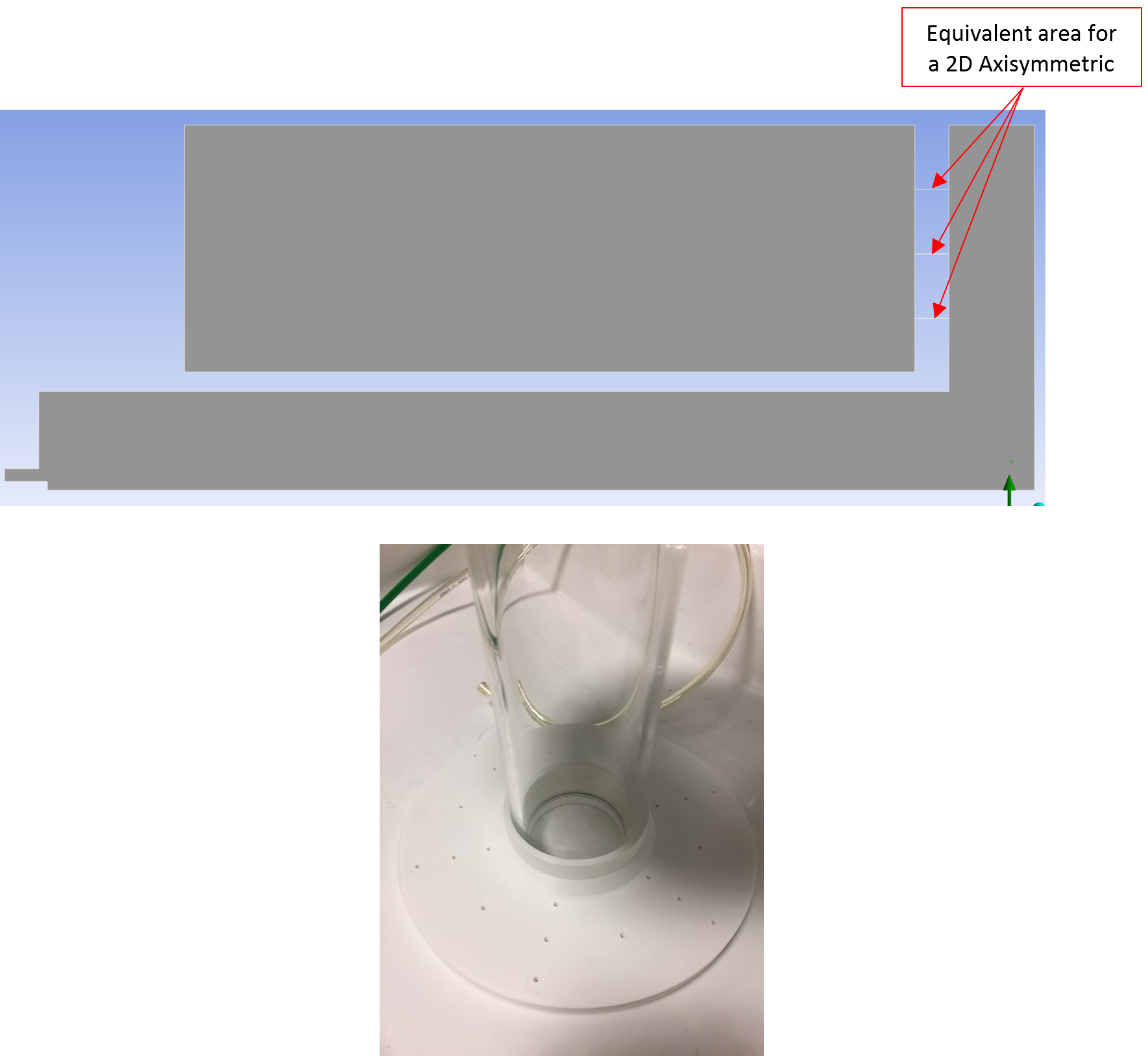
SubscriberI'm trying to simulate a cylindrical vessel with water that contains a horizontal plate with holes near the bottom and an inlet-tube at the centre. Through the tube, air at 70 l/min flow rate enters the vessel, under the plate. Then the air goes though the holes in the plate (4 mm diameter) and bubbles are created into the vessel. The aim is to determine the interface area (air-water).
I’ve created a revolved geometry with a 10º sector of the system, i.e. only a slice of the system. I’ve used sweep mesh everywhere except in the plate holes. So, the mesh is not conformal from one side to the other. I’ve used a “Periodic” boundary condition.
December 21, 2021 at 2:55 pmRob
Forum ModeratorGiven you're using VOF you'll need a lot more mesh to capture the bubbles, and the transient solver as their position will vary with time. Otherwise the flow looks plausible for the configuration.
December 21, 2021 at 4:43 pmSubscriberThank you Rob. Yes, I'm using Transient solver.
So, I will continue improving the model based on th VOF.
Thank you again.
December 21, 2021 at 4:56 pmForum ModeratorIf you want to track the free surface, then yes use VOF. If you're expecting the bubbles to be small you may want to review multi-fluid VOF. The choice of model is dependent on what you want to see, and the level of mesh refinement you can afford.
December 21, 2021 at 6:25 pmSubscriberOk. As the model is somehow 3D, the level of mesh refinement can't be that high.
December 22, 2021 at 9:48 amForum ModeratorThere is a cell limit on the licence, but that just means you need a higher level licence & more compute if you want to see the bubbles. You can try modelling half a hole (5 degree sector) using symmetry and reduce the length of the inlet pipe.
Fundamentally, the VOF model requires a very high resolution mesh to track the free surface. With bubbles you're looking at 5-10 cells across the bubble. There's a reason we are careful when defining models as it's not always practical to include everything.
January 10, 2022 at 1:55 pmSubscriberHello Bob I'm trying to simplify the simulation dividing the model. in two parts.
Part 1: Simulate a 2D axisymetric of everything to find the presure at the holes' inlet.
Part 2: Simulate a 3D periodic with only the holes and upper chamber with water to simulate the bubble formation.
What do you thing of this strategy?
Nevertheless, in Part 1 I've enconter with a "problem": As the holes are small (2mm diameter) and there are not too many, the equivalent area of all the holes at each level for the 2D axisymmetric model are very small. Here is a picture of what I mean:
January 10, 2022 at 2:08 pmForum ModeratorI'd be looking at a 3d sector using symmetry and modelling about a 30 degree sector cutting a single & 3 holes on either side of the sector.
2d is good if you don't need to worry about 3d effects: you do as you're modelling small nozzles rather than slots and want to see the local flow. Periodic isn't needed as you're not swirling the flow, if you are then you'll need to model a larger sector and can't cut the holes in half.
January 10, 2022 at 4:31 pmSubscriberThank you for answering so quickly Bob.
No I'm not swirling the flow. So I will use a 3D sector using symmetry as you mentioned.
Thank you very much again.
Alpha
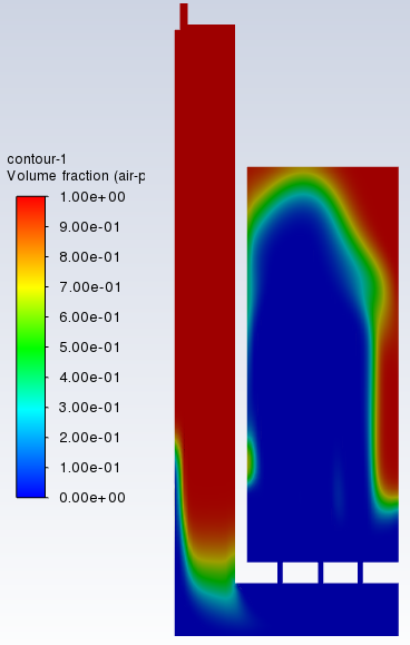
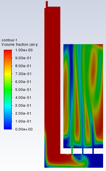
January 12, 2022 at 11:23 pmSubscriberHello again I've simulated the 30┬║ sector with simmetry at both sides. But the results are not what we were expected. The air jet at the imput takes all the wather out of the vassel.
So, I think that in doing a model with only 30┬║ of the geometry and applying simmetry at both sides, only simulates 90┬║ of the geometry (30┬║+30┬║+30┬║=90┬║).
In order to simulates the whole geometry, do I have to simulate half of the geometry and apply symmetry?
What do you think?
Here are some pictures of the results:
January 13, 2022 at 4:43 pmForum ModeratorCheck the velocity field in the model. How good was the convergence?
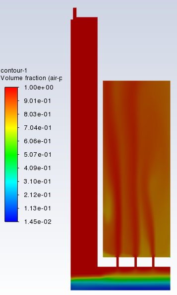
January 17, 2022 at 9:03 amSubscriberHello Bob I've simulated again the 30┬║ sector, with symmetry at both sides, but this time with V_in= V_total/4.
The results looks very good.
Do you think this is correct?
The convergence was smooth, and the velocity field looks also nice.
January 17, 2022 at 12:22 pmForum ModeratorVelocity in the sector should be the same as in the full domain, but this assumes you didn't mis-account for sector when working out the mass flow. I can't comment on 1/4 of the flow being correct: you need to check the mass flow and see what it's doing.
January 21, 2022 at 5:17 pmSubscriberHello Bob I've simulated a simpler model, only with an air input and water at some height in the vessel.
I simulated:
1) A 2D axisymmetric. Inlet Velocity calculated from the flow rate and whole input area à Vel_in = 20.21 m/s. Inlet pressure=500000 Pa. RESULTS: The surface behaviour (water) look as it should. The Flux Report of Mass Flow Rate at the inlet is also right.
2) A 3D, 90┬║ sector and symmetry at both sides. Inlet Velocity equal to the previous case (Vel_in=20.21 m/s). Also, the same Inlet pressure=500000 Pa. RESULTS: The surface behaviour (water) looks the same as case 1 (2D axisymmetric). The Flux Report of Mass Flow Rate at the inlet is ┬╝ of the previous one. Velocity and pressure profiles are identical as in case 1.
3) A 3D, 30┬║ sector and symmetry at both sides. Inlet Velocity equal to the previous case (Vel_in=20.21 m/s). Also, the same Inlet pressure=500000 Pa. RESULTS: The surface behaviour (water) looks the same as case 1 (2D axisymmetric). The Flux Report of Mass Flow Rate at the inlet is 1/12 of the previous one. Velocity and pressure profiles are identical as in case 1.
Conclusion: If you use a 3D sector with symmetry, you have to use the whole velocity and pressure. Also, you have to multiply the Mass Flow Rate by 360/┬║Sector to get the equivalent Mass Flow Rate (whole 3D geometry).
January 21, 2022 at 5:28 pmForum ModeratorYes. And you'll be surprised how many people don't realise that.
March 29, 2022 at 10:43 amSubscriberHello again Rob I have simulated the model we have been discussing and there is still some issues that I have to fix. I'm workng on them...
Nevertheless, right now I am not able to see the inlet pressure I have defined. I wanted to display it through a contour plot.
My inlet pressure is 500000 Pa, and the inlet velocity is 8 m/s. IÔÇÖm able to see the inlet velocity in a contour plot, but not this pressure value (500000Pa).
I attach some picture of the pressure contour plot.
IÔÇÖll be very grateful if you can help me with this issue.
Alpha
March 29, 2022 at 10:56 amForum ModeratorI'm still not allowed to download attachments! Please repost the images.
March 29, 2022 at 11:12 amSubscriberI'm sorry. I forgot that. I attache them now:
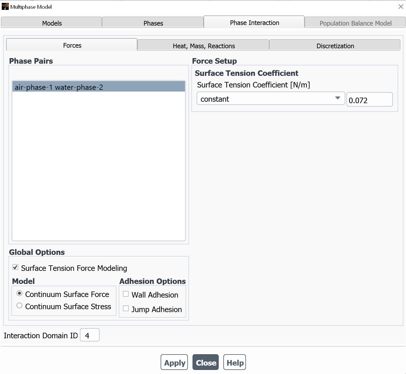
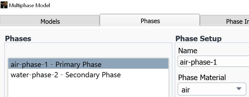
March 29, 2022 at 1:33 pmForum ModeratorWhat are the boundary and operating conditions set as? Screen grabs are easiest to check.
March 29, 2022 at 2:54 pmSubscriberHere some screen grabs of the model:
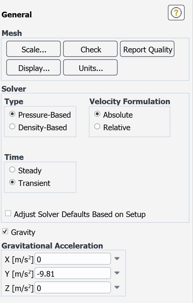
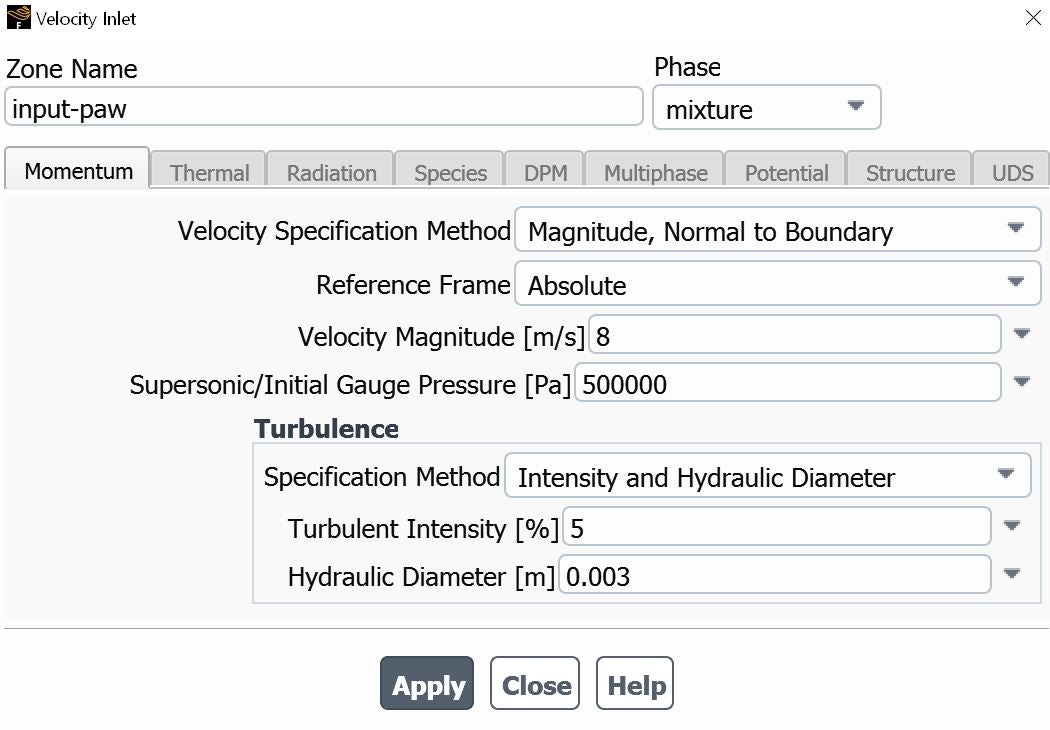
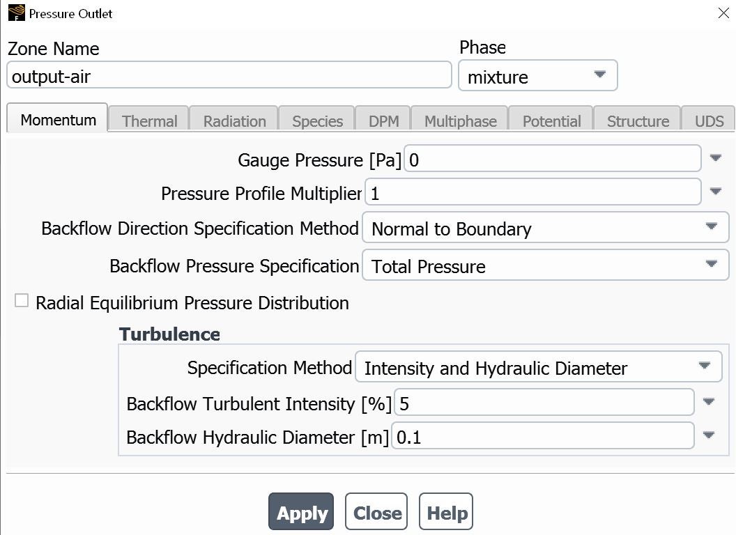
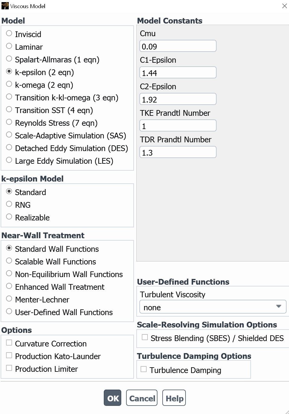
March 29, 2022 at 4:09 pmForum ModeratorRead the pressure option on the velocity boundary carefully, then read the Help links from that panel. It's not doing what you think it's doing.
April 6, 2022 at 9:18 amSubscriberDear Rob, yes, you are right... as always. So, I have set only the Velocity at the input. According to what IÔÇÖve read, the pressure is adjusted by Fluent in order to get that velocity.
Thank you for you help. I'm closer to the final model. I have introduced the inlet velocity progressively and in this way there are no instabilities (a problem that happened when I set the full velocity at the inlet).
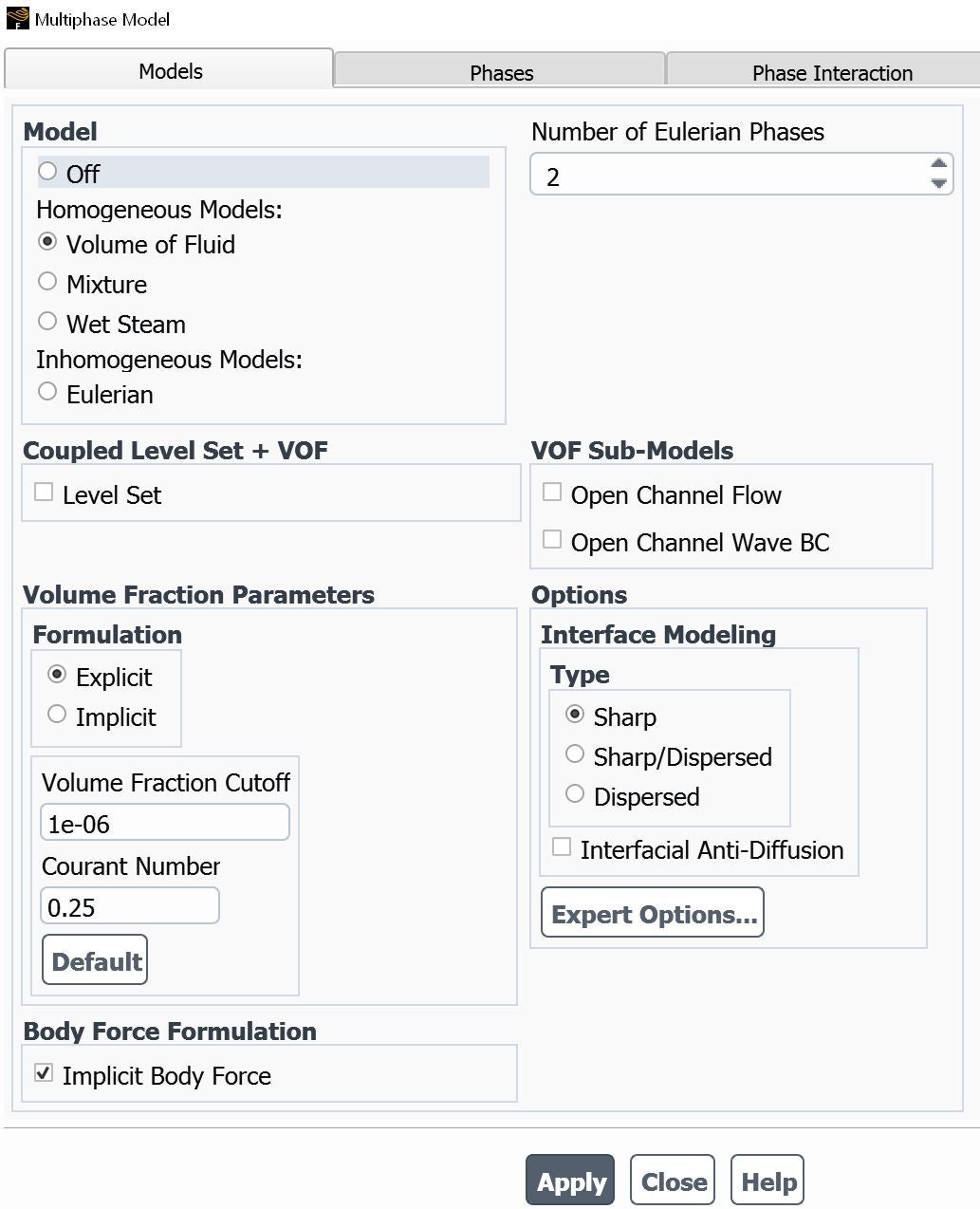
Now I need to get bubbles coming out from the small tubes. The bubble at the experiment (real life) are quite big, so I think the mesh I have now should be enough.
...Maybe I have to use the Eulerian multiphase model
A question: How can a get the Courant number. In this video https://www.youtube.com/watch?v=RO5IGUvgNoU&t=845s, it says that it should appear at the beginning of the calculation. But I donÔÇÖt get it. Maybe I have to check to display this value somewhere.
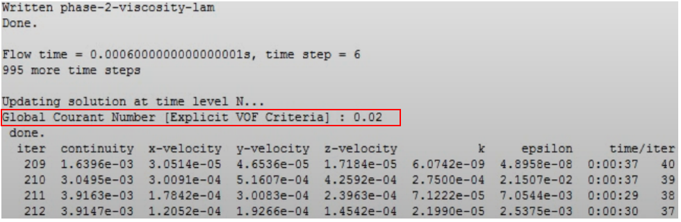
April 6, 2022 at 2:20 pmForum ModeratorFluent should report the Courant Number (it's related to the time step size) when the VOF model is switched on.
March 21, 2023 at 12:43 pmSubscriberHello,
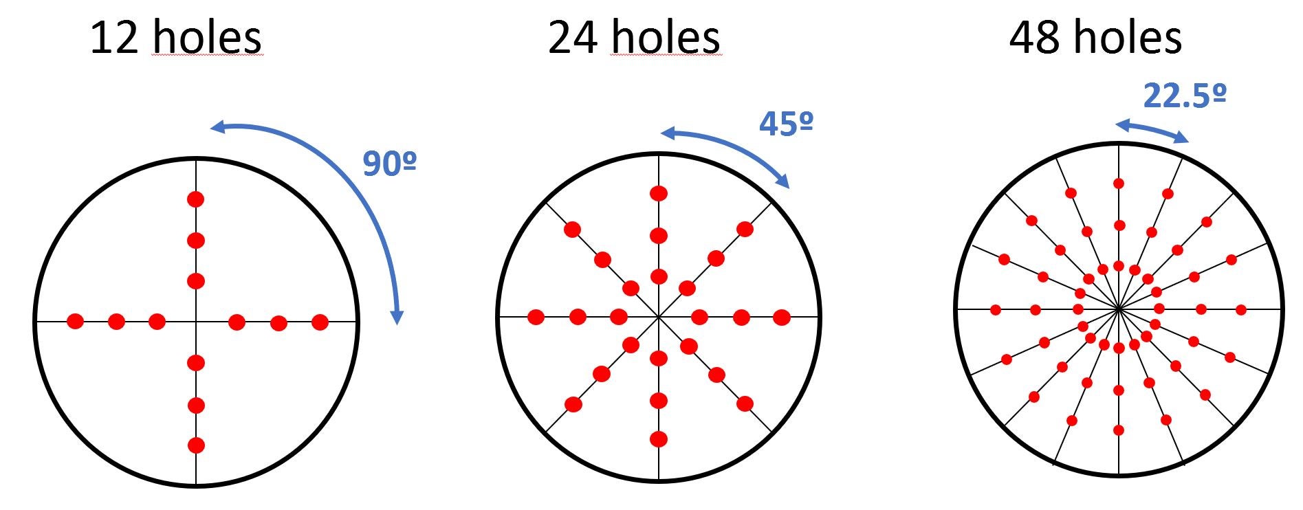
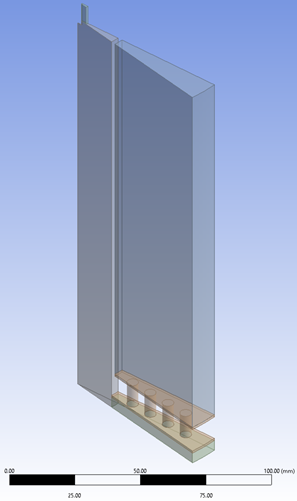
I've simulated the same tank but using a different plate with holes in each simulation. The only difference is the number of holes in each plate. All holes are aligned along the radius, and the number of holes per "line" is 3. There are different plates: with 48, 24 and 12 holes.
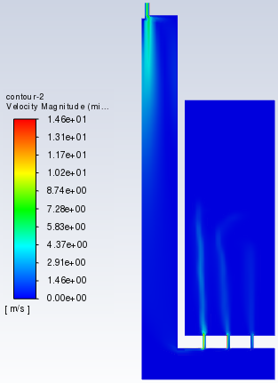
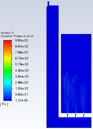
So, the tank contains watter up to a certain level. The air comes from the upper side of the model, pass through the holes of the plate and form bubbles. I have simulated the three plates (with 48, 24 and 12 holes). I've simulated only a sector. For 48 holes: 22,5 degrees; for 24 holes: 45 degrees and for 12 holes: 90 degrees. You can see it in the images below.
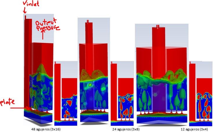
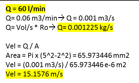
The Velocity inlet (15.16 m/s) was calculated according to the Inlet Flow rate: 60 l/min. The outlet pressure is 0 Pa.
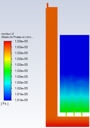
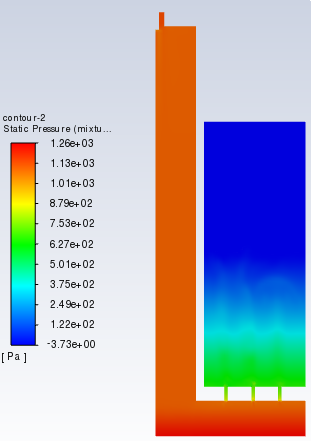
So, the highest pressure through each hole should be when using the 12-hole plate. And the lowest pressure, when using the 48-hole plate. Right?
Below there are some simplified calculus:
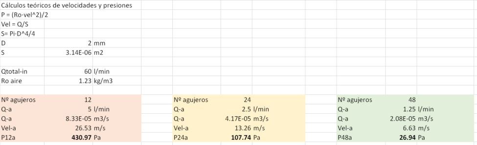
But the simulation ofered these average values (in the hole nearer the center tube. The rest of the holes offered similar reults):
P12a-sim= 1036 Pa
P24a-sim= 729 Pa
P48a-sim= 691 Pa
I know that should be more variables involved in the calculus, but what seems wrong to me is that the average presures resulting when using 24 holes and the one using 48 holes are too high and almost the same.
What could be wrong?
Thank you in advance for your help.
Alpha
Viewing 23 reply threads- The topic ‘Simulating air’ is closed to new replies.
Ansys Innovation Space Trending discussions
- air flow in and out of computer case
- Varying Bond model parameters to mimic soil particle cohesion/stiction
- Eroded Mass due to Erosion of Soil Particles by Fluids
- I am doing a corona simulation. But particles are not spreading.
- Centrifugal Fan Analysis for Determination of Characteristic Curve
- Guidance needed for Conjugate Heat Transfer Analysis for a 3s3p Li-ion Battery
- Issue to compile a UDF in ANSYS Fluent
- JACOBI Convergence Issue in ANSYS AQWA
- affinity not set
- Resuming SAG Mill Simulation with New Particle Batch in Rocky
Top Contributors
-
peteroznewman
 3977
3977 -
scabo
 1461
1461 -
Dennis Chen
 1272
1272 -
javat33489
 1124
1124 -
Shyam Prasad V Atri
1021
Top Rated Tags
© 2025 Copyright ANSYS, Inc. All rights reserved.
Ansys does not support the usage of unauthorized Ansys software. Please visit www.ansys.com to obtain an official distribution.
-

Fluids
Topics related to Fluent, CFX, Turbogrid and more.
Simulating air


Ansys Assistant

Welcome to Ansys Assistant!
An AI-based virtual assistant for active Ansys Academic Customers. Please login using your university issued email address.

Hey there, you are quite inquisitive! You have hit your hourly question limit. Please retry after '10' minutes. For questions, please reach out to ansyslearn@ansys.com.
RETRY