General Mechanical

General Mechanical

Topics related to Mechanical Enterprise, Motion, Additive Print and more.

How to apply a radial force on a curved beam?

    • rhylane.civil
      Subscriber

      Hello everyone! I want to apply a radial load on a curved beam but I don't know exactly how can I do it. Please can someone show me how to do this? Thank you.

    • peteroznewman
      Subscriber
      Create a cylindrical coordinate system. The X axis is radial, so apply a Force using Components in the Cylindrical Coordinate System and enter the value in the X component, leaving Y and Z at 0.
    • rhylane.civil
      Subscriber
      Thank you so much dear peter for your answer, but i didn't know how to define a cylindrical coordinate system.
      I did like it says in the Ansys help: i clicked with the mouse right button on thecoordinate system objectand then i selected inset>coordinate system. After that, in the details view>Definition>Type, i selected cylindrical. Then in Details view>Origin>Defined by i selected the geometry selection and i choosed the end of the beam. The figure below show the result of these steps. The direction of the radial force which i need to apply is as shown on the same figure. It's component is along the z axis. After this step, i don't know how to continue. Could you help me please sir?

    • peteroznewman
      Subscriber
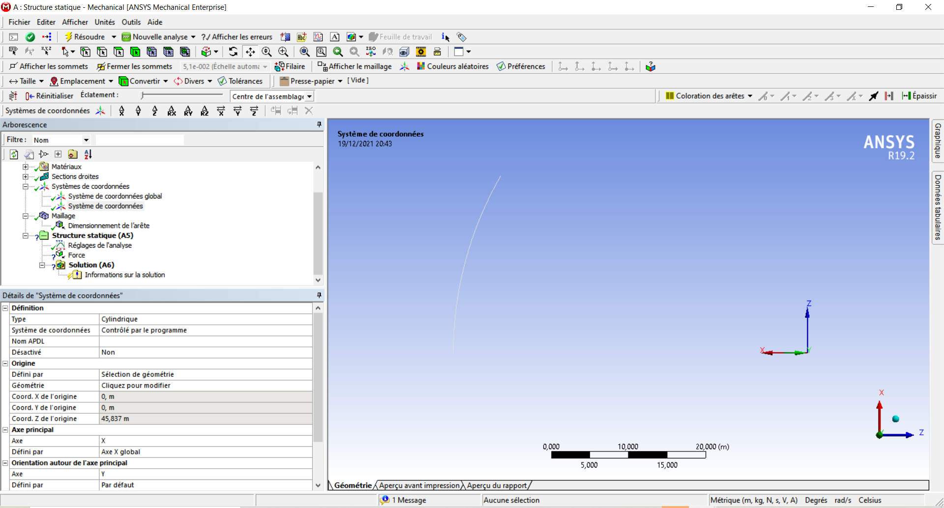
      The geometry to select for the origin is the curve, not the vertex. That will snap the origin to the center of the circle, where it must be.
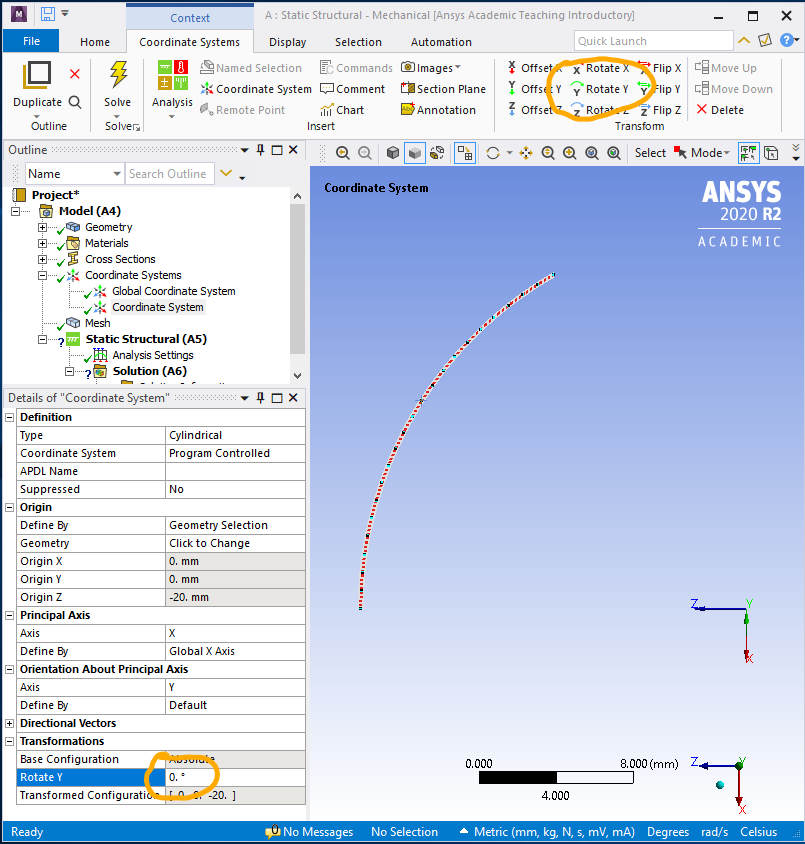
      In the image below, I have created the cylindrical coordinate system, but the direction of the axes are not correct, only the origin is correct. The menu ribbon is on the Coordinate Systems tab, not the Home tab. You can see a set of transforms on that ribbon. In my case, I need to rotate about the Y axis -90 degrees to make the X axis radial, so I click on the Rotate Y button. Type in -90 where the 0 is circled and hit enter, the Coordinate system will rotate.
    • rhylane.civil
      Subscriber
      really thank you so much dear,by following the steps you showed to me i obtained the following picture. But I don't know why I didn't find the cylindrical coordinate system I created among the choices when I selected, in the Details '' Force '', Definition> coordinate system.

    • peteroznewman
      Subscriber
      You haven't oriented your Cylindrical Coordinates properly. If you had, the green theta axis would be in the same plane as your curve.
      I misunderstood, I thought you wanted to apply the force to the entire curved beam, like a distributed force. You can use the Cylindrical Coordinate Frame to do that.
      If you only want to apply the force to the vertex, you must use Global Coordinates. In the image below, the vertex is 45 degrees up from the X axis so two components of equal value represent 100 N radially.
    • rhylane.civil
      Subscriber
      Thank you so much sir for your helpful answers; so i can understand now that in my case , for applying a radial force in a vertex i don't need to create a cylindrical coordinate system because i can do it only by calculing and entering the Fx and the Fz componnents of the radial force. Please sir, If i want to calculate the radial displacement of the end of the beam caused by this radial force , how can i do it?
    • peteroznewman
      Subscriber
      If you repair your cylindrical coordinate system, you use that in a Directional Deformation plot in the X direction.
    • rhylane.civil
      Subscriber
      Thank you so much sir for your help and your support. Thank you so much.
Viewing 8 reply threads
  • The topic ‘How to apply a radial force on a curved beam?’ is closed to new replies.