TAGGED: peteroznewman
-
-
December 12, 2021 at 10:01 am
tumulpurwar
SubscriberHello peter
If my 25 % of ship structure(which is made of shell elements) is fixed on both sides( by fixing all edges of cut section on both side by fix support option in ansys.
What it signifies?
Translation fix but all rotation free?
Or
Translation fix and all rotation fix too?
December 12, 2021 at 12:53 pmpeteroznewman
SubscriberFixed Support for shell and beam elements means translations and rotations are fixed.
December 12, 2021 at 1:18 pmtumulpurwar
SubscriberThanks a lot
Just one more wish
In case of shell element, if in bottom of vessel(bottom plate) of 25% ship which also need to be fixed to stop rigid body motion, if I select complete bottom face, and put fixed support
And
If just select edge of bottom shell plate, which is edge coming due to two bottom plates joined together in midship of 25 % modelled ship, what will be difference?
Is fixing edge in case of shell element or otherwise do fixed support to face of bottom plate makes any difference in dof free and fixed?
December 12, 2021 at 1:22 pmpeteroznewman
SubscriberIf the two cut planes at each end of the 25% model have fixed support, rigid body motion has been fixed and there is no need to do anything with the bottom of the vessel.
December 12, 2021 at 1:39 pmtumulpurwar
SubscriberIn my case peter, I have only crane load acting on deck, and hydrostatic pressure acting up ,the difference of both will create buoyancy, as well as bending longitudinally, so do you think, fixed support on both ends of ship is correct?
That's true. I totally forgot to remember, now the model which I took, its not complete upto bottom baseline.so in current case I fixed bottom.
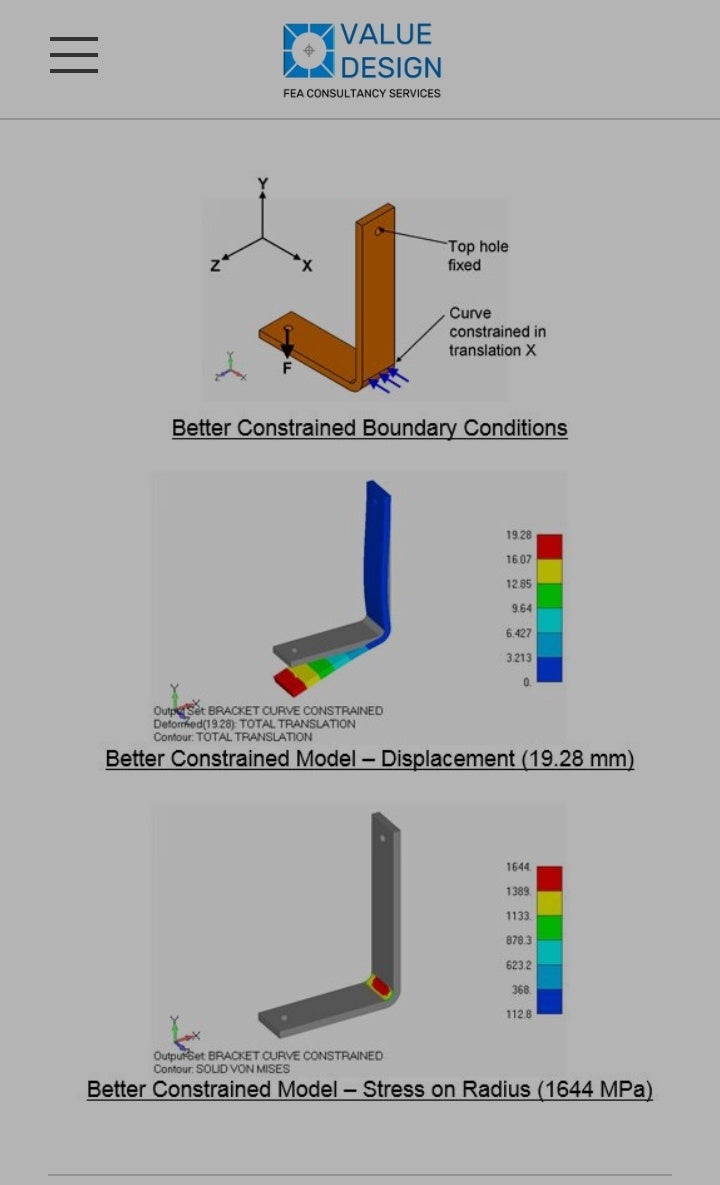
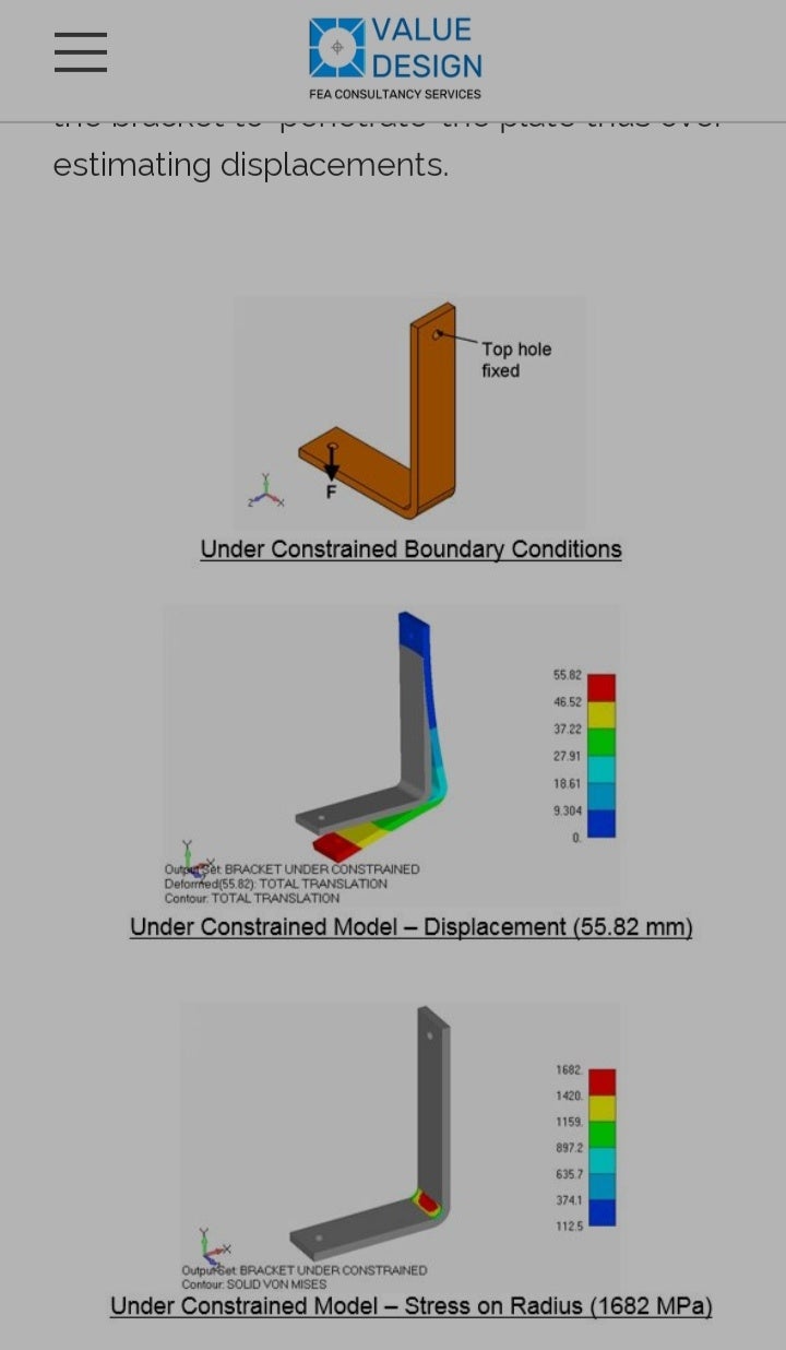
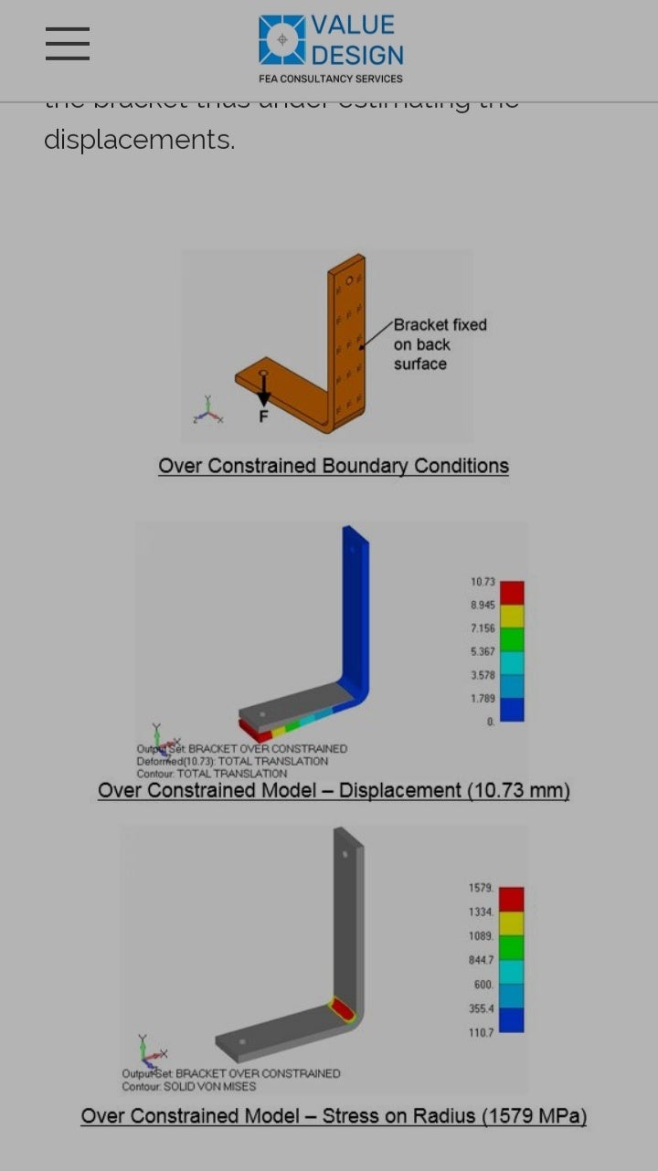
I attach photo of one of very nice example(when to fix edge, when to fix complete face)
Please if you can tell, how shell, beam and solid, I should fix, like when to fix their edge or when to fix complete face. And do fixing only edge or otherwise only face, change dof of constraint which we applied for particular application?


December 12, 2021 at 1:49 pmpeteroznewman
SubscriberIt's fine to apply displacements to points on beams, edges on shells and faces on solids.
It's very bad to apply displacements to a point on a solid.
It's bad to apply displacements to an edge on a solid.
Both cases introduces a stress singularity into the model where the value of stress depends on the element size because the force is being divided by geometry (point or edge) with zero area.
December 12, 2021 at 2:01 pmtumulpurwar
SubscriberThank you
December 12, 2021 at 2:01 pmRameez_ul_Haq
Subscriber,and this introduction of stress singularity will only be seen on and near the elements where this force itself is applied, right?
December 12, 2021 at 2:19 pmpeteroznewman
SubscriberYes. local stress near the point or line.
If you don't care about the stress at the fixed supports and only care about the local stress near the crane supports, then fixed supports is easier.
Buoyancy is the vertical component of hydrostatic pressure.
December 12, 2021 at 2:21 pmtumulpurwar
SubscriberI understood
Thankyou
December 12, 2021 at 3:47 pmtumulpurwar
SubscriberHello Peter, you told in previous comment:
It's fine to apply displacements to points on beams, edges on shells and faces on solids.
I applied few days back vertical load on edge of shell element (in case of I rail on its top flange)
 It created stress singularity also.
Than I replaced I section rail made up of shell element to beam(line element) I section, than I applied point load, than it gave normal value
February 1, 2022 at 7:39 pmRameez_ul_Haq
Subscriberhave a look at the comment I quoted above, that you have made here. Can you kindly explain why would applying displacement constraints or force at a node (or point) on beams and at a line on shell will not give any singularity? Because you said in the same comment that, 'because the force is being divided by geometry (point or edge) with zero area'. Well, for the case of displacement constraint or a force on a single node on beam or a line on shell wouldn't eventually mean that the force is being divided by zero area?
February 1, 2022 at 11:12 pmpeteroznewman
SubscriberA node attached to a solid element has zero area, so a force applied to a single node on a solid element creates a singularity. If the force is divided into four nodes on one face of a hex element, now there is a non-zero area to divide by and avoid a singularity.
A node attached to a shell has the thickness of the shell so in-plane forces are being spread over the thickness. Two nodes on the edge of a shell element have the thickness times the element edge length, which is a non-zero area.
A single node of a beam has the entire cross-sectional area assigned to the beam element.
February 2, 2022 at 6:39 amRameez_ul_Haq
Subscriber,well that explains. Thanks.
I want to understand the mathematical formulation of stress singularity and why does it appear. What you are saying makes sense for a general conversation and an overall understanding of the idea behind it, but how does FEA reflect what you said through mathematics is something I would love to learn. Because I have already searched so many popular books on FEA, engineering and FEA forums but still I didn't catch any luck where I could get my hands on the mathematics behind singularity and its effects.
February 2, 2022 at 1:37 pmpeteroznewman
SubscriberSingularity just means that as element edge lengths tend toward zero, the stress tends toward infinity. In the example of the four nodes on the face of a hex element having a non-zero area, that is only true if the geometric area is maintained as the elements get smaller. For example if the edge length is cut in half, then the force is spread over 9 nodes to cover the same area as the original 4 nodes. If the edge length is cut in half again, now the force is spread over 25 nodes.
If the force remains on just 4 nodes, that would create a singularity because the force remains the same, but the area is tending toward zero.
February 2, 2022 at 7:34 pmRameez_ul_Haq
SubscriberIf the force remains on just 4 nodes, that would create a singularity because the force remains the same, but the area is tending toward zero.
You mean the that would create stress concentration, right? I mean not a singularity, right? Because doesn't matter how much smaller I make the element size, but if I keep the forces on the same 4 nodes, then it will never result in a singularity but ofcourse the stress concentration will become more intense.
Viewing 15 reply threads- The topic ‘Shell boundary condition’ is closed to new replies.
Innovation SpaceTrending discussionsTop Contributors-
4597
-
1500
-
1386
-
1209
-
1021
Top Rated Tags© 2025 Copyright ANSYS, Inc. All rights reserved.
Ansys does not support the usage of unauthorized Ansys software. Please visit www.ansys.com to obtain an official distribution.
-


