TAGGED: additive-manufacturing, contacts, static-structural
-
-
December 12, 2021 at 9:54 am
Munchy99
SubscriberDear All,
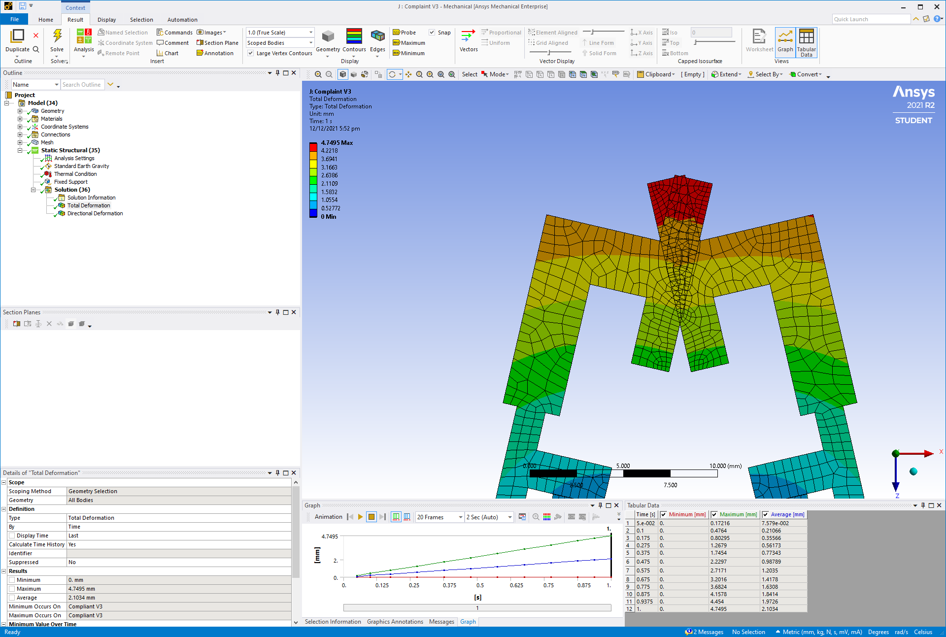
I am working on my FYP which is a 4D printed Microgripper, my model is in static structural analysis. I had tried to configure the contact in frictional, frictionless and others, but the tips of the gripper still penetrated towards each other. As for other parts that were bonded, the contact settings seems to be working fine.
Does anyone has any idea how to solve this? ?
December 12, 2021 at 1:24 pmpeteroznewman
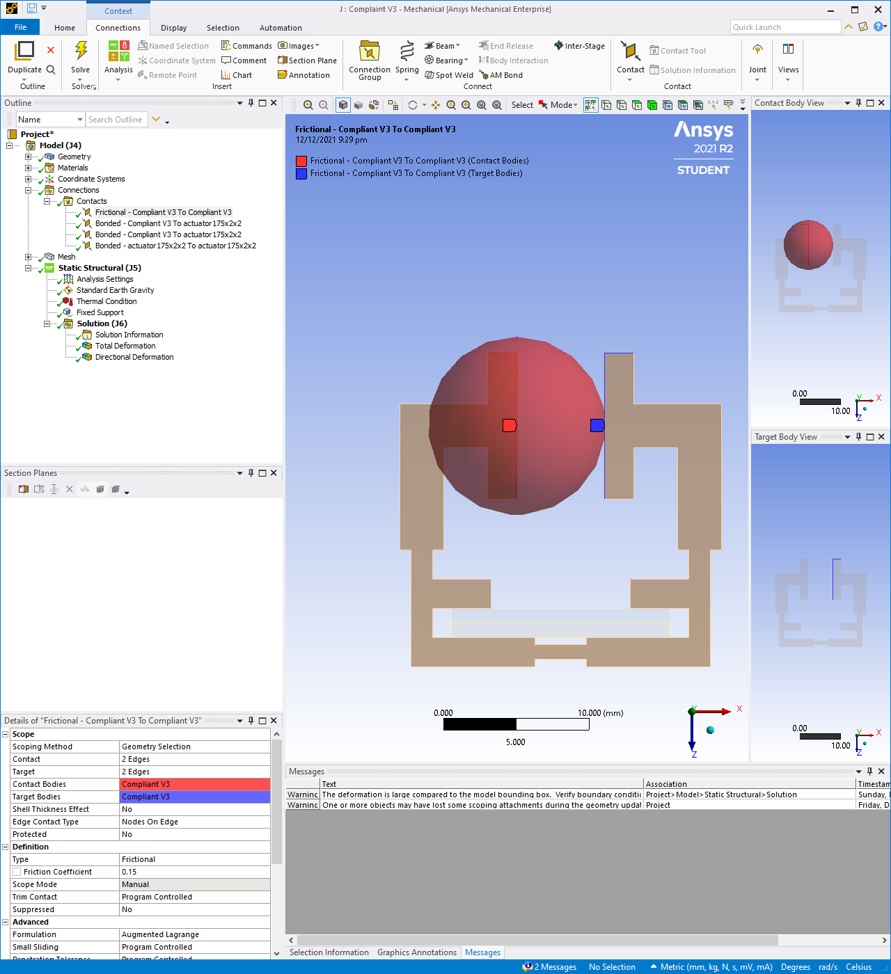
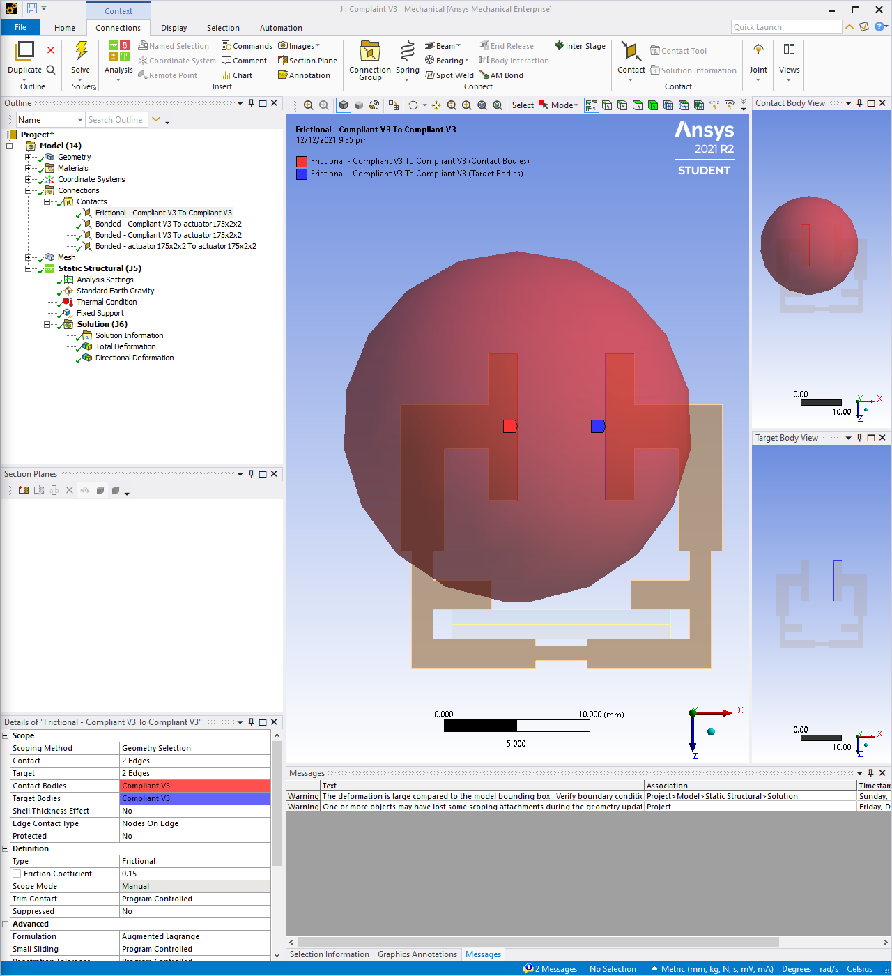
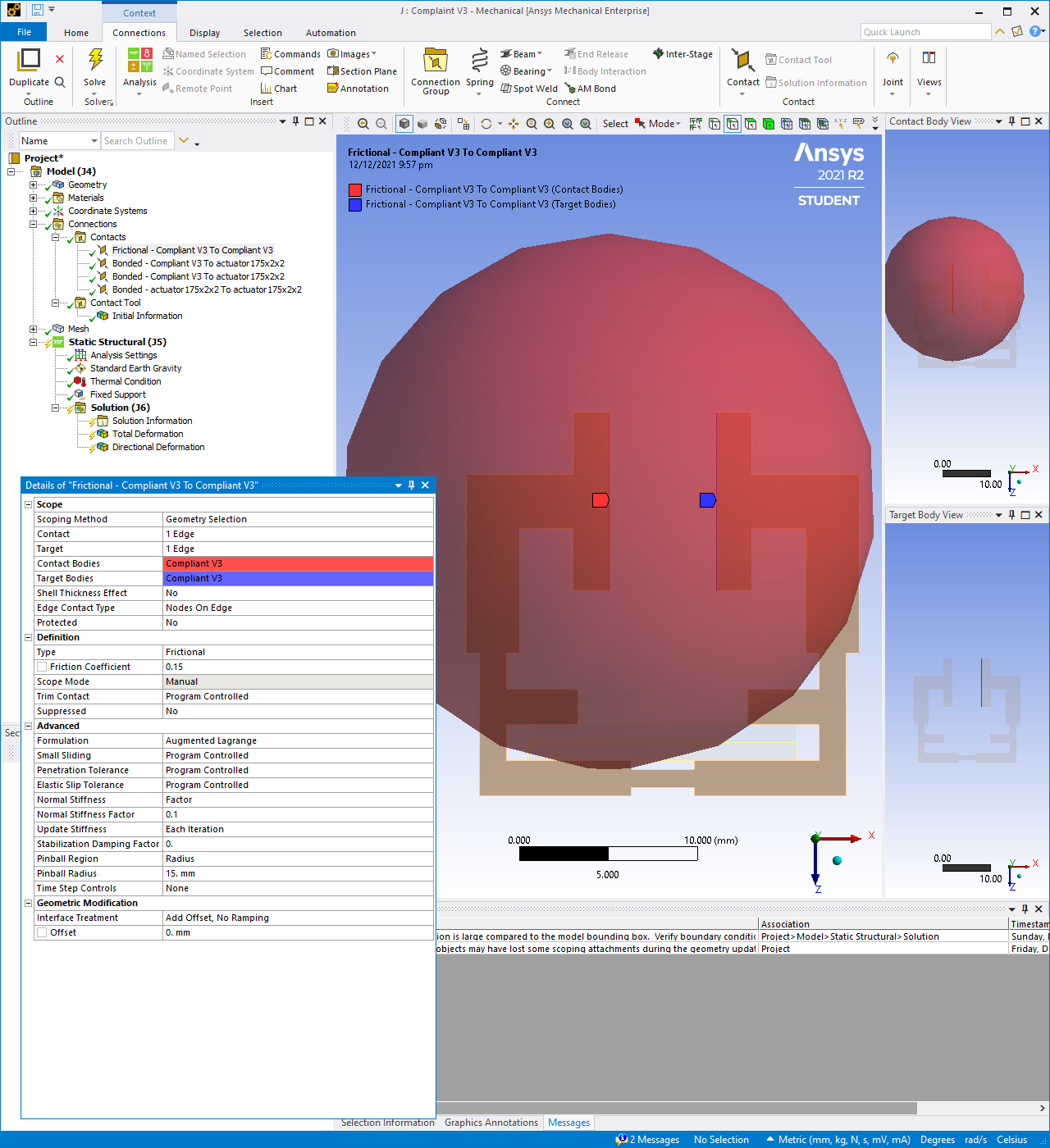
SubscriberIn the Details window for the Frictional Contact is a line called Pinball Radius. You need to enter a value of the radius that is larger than the distance between the two surfaces. The pinball is shown as the red sphere. The red sphere has to reach the blue surface for the contact to be included in the simulation.
December 12, 2021 at 1:32 pmDecember 12, 2021 at 1:34 pmpeteroznewman
SubscriberDouble the size of the pinball radius.
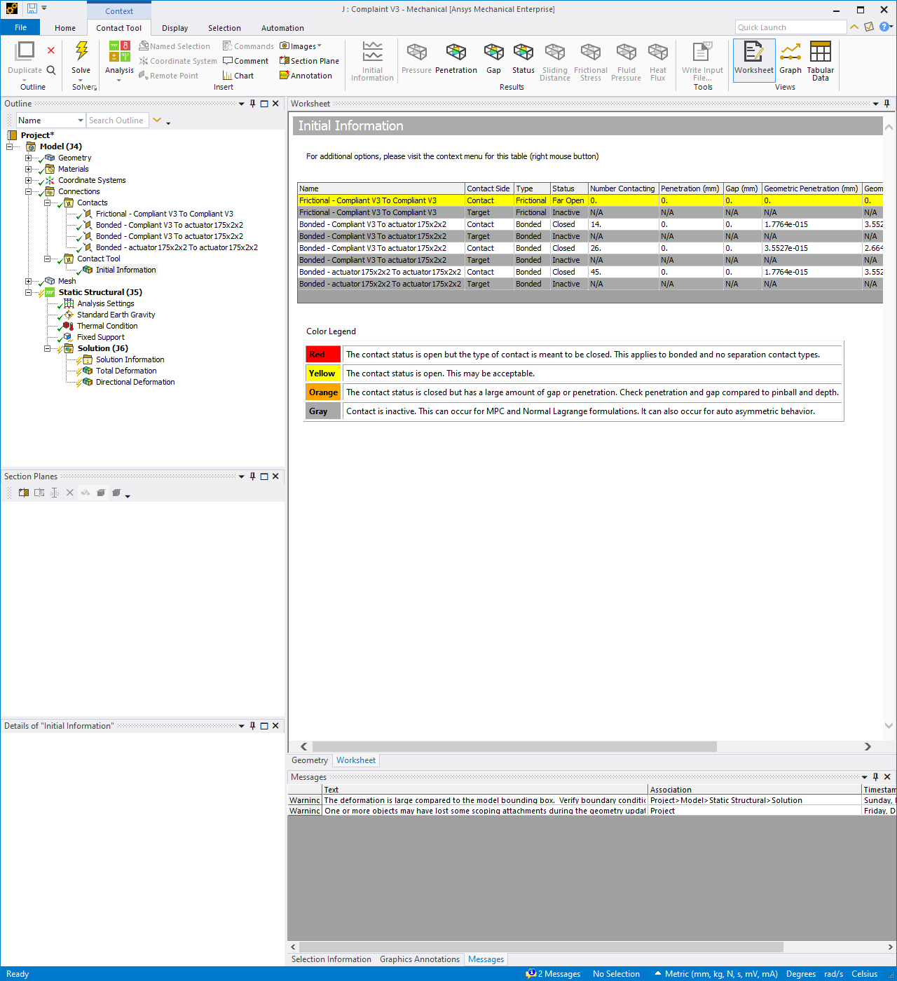
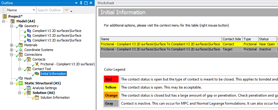
Under the Connections folder, insert a Contact Tool, then Generate Initial Contact Status and see if the contact lists as Near Open. That means it will be included in the simulation.
If you make the Pinball radius small, and Generate Initial Contact Status again, it will be Far Open. That means it will not be included in the simulation.
December 12, 2021 at 1:35 pmDecember 12, 2021 at 1:38 pmpeteroznewman
SubscriberUnder the Connections folder, insert a Contact Tool, then Generate Initial Contact Status and see if the contact lists as Near Open. That means it will be included in the simulation.
If you make the Pinball radius small, and Generate Initial Contact Status again, it will be Far Open. That means it will not be included in the simulation.
Under the Analysis Settings, turn on Large Deflection
December 12, 2021 at 1:42 pmDecember 12, 2021 at 1:56 pmpeteroznewman
SubscriberTry removing the short horizontal surface at the top from the contact and target sides of the definition, keep just the single large surface on each side.
If that doesn't fix it, you need to change some settings in the Details window that are cut off in your image.
December 12, 2021 at 2:00 pmDecember 12, 2021 at 2:13 pmpeteroznewman
SubscriberI see now that you have a surface body, and are trying to make the edges contact. What are the choices under Edge Contact Type?
Do you need this model to be in 3D? I suggest you solve it as a 2D model, then the contact would work.
To build a 2D model, you have to start fresh in the Geometry editor, and rotate the surfaces into the XY plane.
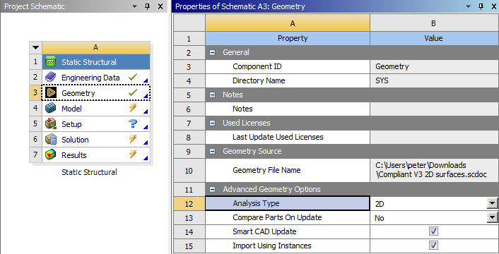
Start a new Static Structural model, and in Workbench, click the Geometry tab and in the Properties window, set the Analysis Type to 2D.
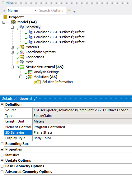
After you open the model in Mechanical, you set the type of 2D analysis to Plane Stress for thin parts in the z-direction or Plane Strain for very thick parts.
December 12, 2021 at 3:34 pmMunchy99
SubscriberI actually tried to set the face contact first in the 3D model, but I found some guy saying that converting to mid-surface 2D would work.
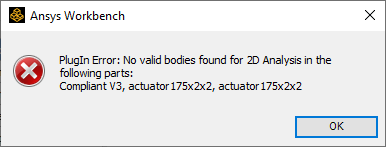
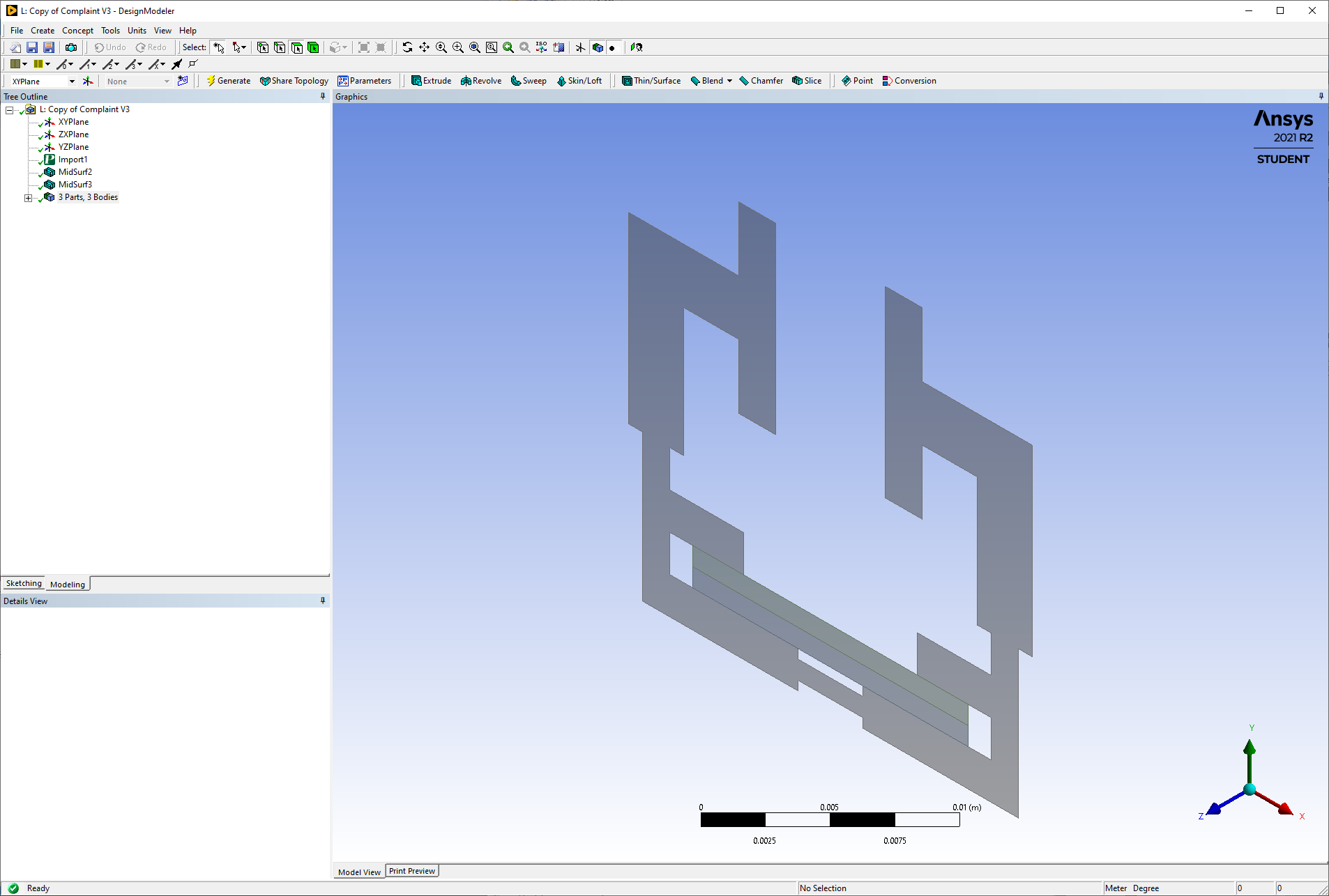
Now that I rotated the sketch and the Mechanical cannot read my model.
(I drew my 3D model in Solidworks and imported as parasolid)
But I would prefer it as a 3D model.
December 12, 2021 at 3:43 pmpeteroznewman
SubscriberAre the surfaces at Z=0?
Please put the Parasolid file into an archive .7z or .rar and attach it to your reply.
December 12, 2021 at 4:28 pmMunchy99
SubscriberMy bad, the surface are not at z=0, I tried to shift it, but it is still at z = 0.001mm. I have attached the file.
I am not familiar with Design ModelerDecember 12, 2021 at 6:52 pmDecember 13, 2021 at 3:41 amMunchy99
SubscriberThank you very much!!! I will look into tutorials for drawing in design modeler/ space claim, may I know how u repair the alignment?
December 13, 2021 at 12:34 pmpeteroznewman
SubscriberIn SpaceClaim, I put the three components into a new component. Created a plane on the XY plane. On the Assembly Tab, I used the Tangent button and the Align button.
The design is to clamp an object. It would be a more realistic model if you put an object, such as a circle, in the center for it to clamp against. The circle could be the Target, the two flat faces of the clamp can be the Contact side of a Frictional Contact.
December 13, 2021 at 4:03 pmMunchy99
SubscriberAlright, I will try it. I also thought about putting the circle to analyze force. Thanks a lot for your help sir.
Viewing 16 reply threads- The topic ‘Why my contact is not working?’ is closed to new replies.
Innovation SpaceTrending discussions- LPBF Simulation of dissimilar materials in ANSYS mechanical (Thermal Transient)
- Real Life Example of a non-symmetric eigenvalue problem
- How can the results of Pressures and Motions for all elements be obtained?
- BackGround Color
- Contact stiffness too big
- Element Birth and Death
- Python-Script to Export all Children of a Solution Tree
- Which equations and in what form are valid for defining excitations?
Top Contributors-
4592
-
1494
-
1386
-
1209
-
1021
Top Rated Tags© 2025 Copyright ANSYS, Inc. All rights reserved.
Ansys does not support the usage of unauthorized Ansys software. Please visit www.ansys.com to obtain an official distribution.
-
The Ansys Learning Forum is a public forum. You are prohibited from providing (i) information that is confidential to You, your employer, or any third party, (ii) Personal Data or individually identifiable health information, (iii) any information that is U.S. Government Classified, Controlled Unclassified Information, International Traffic in Arms Regulators (ITAR) or Export Administration Regulators (EAR) controlled or otherwise have been determined by the United States Government or by a foreign government to require protection against unauthorized disclosure for reasons of national security, or (iv) topics or information restricted by the People's Republic of China data protection and privacy laws.

