TAGGED: ansys-mechanical, bolt, bolted-connection, rotation, shear-stress
-
-
December 5, 2021 at 11:12 pm
NPDan
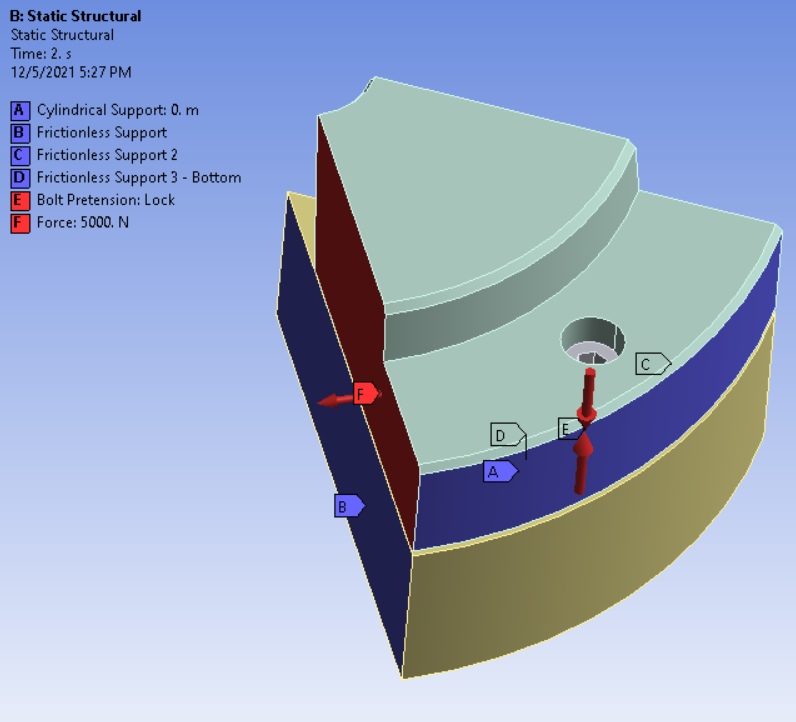
SubscriberI'm a student learning Ansys currently. I am working on a project where I would like to analyze shear stress on a bolt in a bolt circle due to rotation of one of the bolted bodies. This is to simulate shear stresses on a bolt in a lathe chuck due to tangential forces.
I have worked on this model for several hours, I have had to introduce myself to contact features, cylindrical supports, bolt pretension, and shear probing.
I have a model that solves, and produces shear stress values that are reasonable (I believe) based on a simple analytical calculation for shear stress on cylindrical bodies. The equation is the general solution for average shear stress on a cylindrical body : Tau = (4 * F) / (pi * D^2).
For a force of 5000 N, and a bolt diameter of 10 mm (M10 hex cap), this equation evaluates to 63.66 MPa.
The Ansys shear stress tool is applied to a volume of elements and only captures the threaded body of the bolt. The maximum shear stress is 69.23 MPa. This is deviation is acceptable, but I have a feeling I am not modelling this entirely correctly, mainly based on the distribution produced. It is extremely uniform and only has several small points of concentration.
I am modelling a sixth of the entire assembly, with frictionless supports on the spindle (bottom body) on both sides of the 60 degree section, and 1 frictionless support on the bottom. I have applied a cylindrical coordinate system with the tangential direction set to free for the top body.
December 6, 2021 at 4:49 pmpeteroznewman
SubscriberIf the bolts are tensioned correctly, the friction between the lathe chuck and the lathe mount will prevent any slip between those two parts. The bolts will see only tensile stress.
Viewing 1 reply thread- The topic ‘Shear Stresses on Bolts’ is closed to new replies.
Innovation Space Trending discussions
 Top Contributors
-
peteroznewman
 6435
6435 -
scabo
 1906
1906 -
Dennis Chen
 1457
1457 -
javat33489
 1308
1308 -
Shyam Prasad V Atri
1022
Top Rated Tags
© 2026 Copyright ANSYS, Inc. All rights reserved.
Ansys does not support the usage of unauthorized Ansys software. Please visit www.ansys.com to obtain an official distribution.
-