
-
-
November 24, 2021 at 9:33 am
bharath_reddy1
SubscriberPlease see the below image.
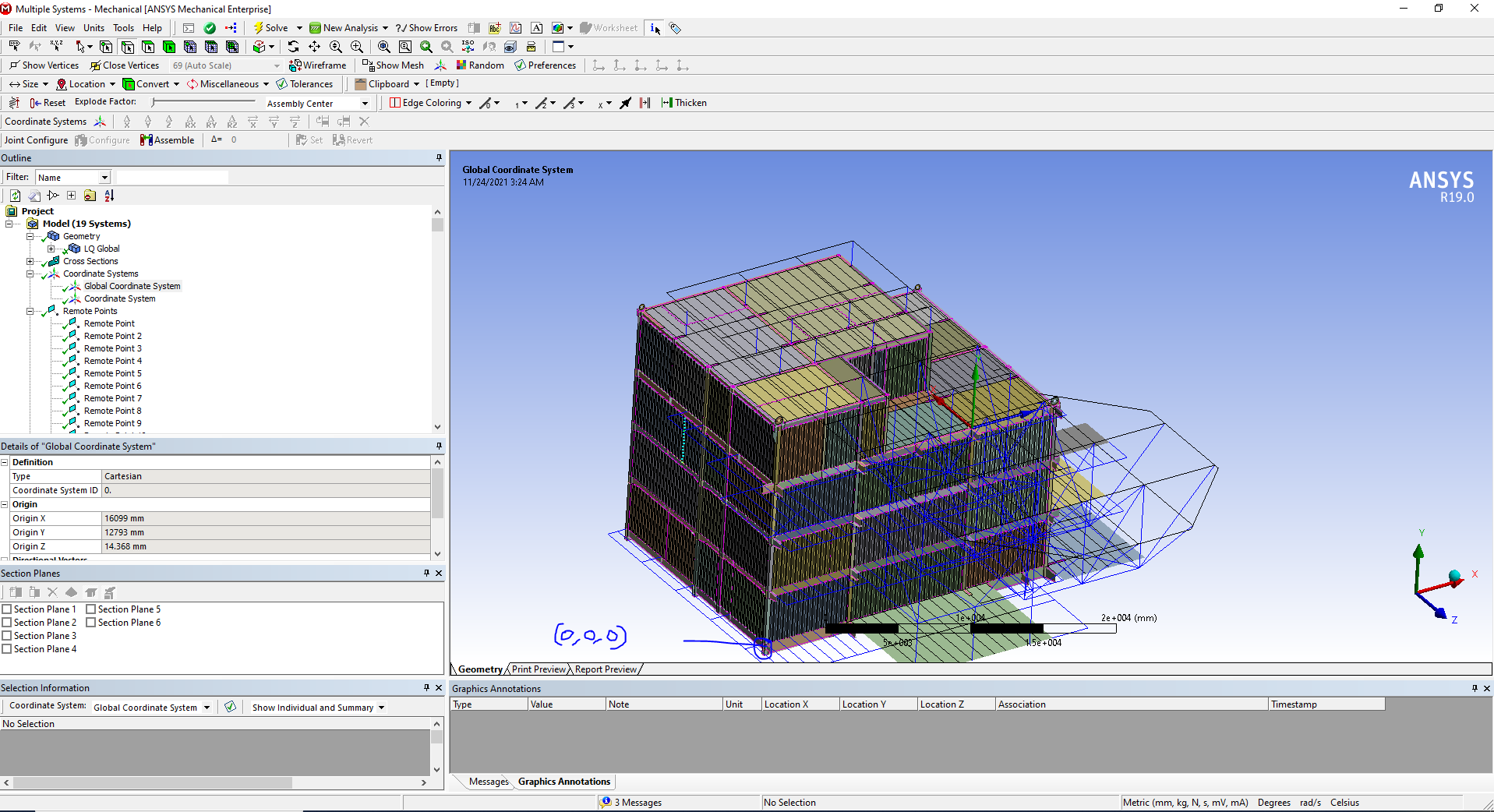
Originally Global Coordinate system is at 0,0,0, location.
Yesterday when i was creating remote points, somehow the location of 'Global Coordinate System' got changed. i dont know how and why it happened, it was not intentional. (even the orientation got changed)
Kindly help me in moving back to the original position and orientation.
November 24, 2021 at 4:35 pmGovindan Nagappan
Ansys EmployeeRight click on Model branch and insert part transform. Then transform the model using the part transform details
Or move the geometry in Design Modeler or Spaceclaim or CAD system
November 26, 2021 at 11:54 amSubscriber
Model is there only its 0,0,0 location did not change, but the Global Coordinate system changed its location. Still do you want me to try this option?
November 26, 2021 at 1:21 pmAnsys EmployeeFor any coordinate system, its origin is always 0,0,0
If the model is in relatively wrong position compared to the coordinate system, you can move the model as needed
Viewing 3 reply threads- The topic ‘Global Co-ordinate System in Mechanical – change in location and orientation.’ is closed to new replies.
Innovation Space Trending discussions
 Top Contributors
-
peteroznewman
 6660
6660 -
scabo
 1906
1906 -
Dennis Chen
 1469
1469 -
javat33489
 1313
1313 -
Shyam Prasad V Atri
1022
Top Rated Tags
© 2026 Copyright ANSYS, Inc. All rights reserved.
Ansys does not support the usage of unauthorized Ansys software. Please visit www.ansys.com to obtain an official distribution.
-


The Ansys Learning Forum is a public forum. You are prohibited from providing (i) information that is confidential to You, your employer, or any third party, (ii) Personal Data or individually identifiable health information, (iii) any information that is U.S. Government Classified, Controlled Unclassified Information, International Traffic in Arms Regulators (ITAR) or Export Administration Regulators (EAR) controlled or otherwise have been determined by the United States Government or by a foreign government to require protection against unauthorized disclosure for reasons of national security, or (iv) topics or information restricted by the People's Republic of China data protection and privacy laws.
