TAGGED: convergence, workbench
-
-
November 7, 2021 at 12:17 pm
Andrew_tan
SubscriberHi,
I am currently running simulation regarding solder joint reliability subjected to temperature cycling. The solder joint will undergo plastic deformation and its behaviour is described by Anand's Viscoplastic model. I have set up all the pre-processing accordingly and the solver is able to run smoothly.
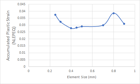
However, when I try to conduct mesh independence study, the results only tend to converge within a certain range of number of elements. When the mesh is too coarse, the value of the result of interest is far away from convergence and when the mesh is too fine, the value of result of interest diverges as well!
May I ask is this the nature of non-linear simulation? This is because I understand that for linear simulation, results tend to converge after reaching sufficiently fine mesh and remains near constant with further refinement. Does non-linear simulation applies the same concept too? What are the other issues leading to the non-convergence?
Attached below is the graph of the result of interest (accumulated plastic strain- NLEPEQ) against element size of the mesh. It can be seen that the results only tend towards a certain value at a specific range of element size. Outside of that range, divergence occurs.
November 7, 2021 at 1:31 pmpeteroznewman
SubscriberFor static structural solutions, element size is varied, but for transient solutions, the time increment is also important. What was the time step used for each of those points on the element size graph?
November 7, 2021 at 1:36 pmNovember 7, 2021 at 1:53 pmpeteroznewman
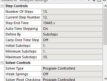
SubscriberMaximum Substeps:Min Substeps allows a 1:10 variation in step size. Endtime/Number of Steps = 803 s, so it was up to the solver whether to use 803 s or 80.3 s on the time step. That may lead to some variation in the result. Time increment may have confounded the effect of element size.
The solution output will show what time increment was actually used by the solver for each time step. Look at that then rerun the Element Size solutions at a fixed time step.
Element size is usually varied on a constant ratio. For example, if the ratio is 2, then you could use 1.6, 0.8, 0.4, 0.2 mm. That gives you four points. You could also use a ratio of 1.5 and use a series such as 0.9, 0.6, 0.4, 0.267 which covers a smaller range.
November 7, 2021 at 2:40 pmAndrew_tan
Subscriber
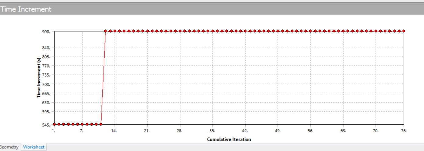
I have looked at the time increment plot given by the solution output. There seems to be only two values 545s and 900s. May I know how to interpret it?
Besides, when you suggested 'Look at that then rerun the Element Size solutions at a fixed time step', do you mean that I keep the element size a constant and rerun the simulation by setting time step either to 545 or 900s in this case to verify its effect on convergence of result in interest?
November 7, 2021 at 7:30 pmpeteroznewman
SubscriberWhich element size is that Time Increment graph for? Do they all end up at 900 s time step or do smaller element sizes have different values of the time increment?
For a specific element size. Run a series of time increment experiments. Change the Initial and Minimum Substeps using this sequence: 1, 2, 4, 8, 16 and see how the Accumulated Plastic Strain changes (you already have the results for 1).
That will be very tedious to setup because you have to do it 13 times to get every Step in the simulation. Please show how the temperature changes over those 13 steps.
November 8, 2021 at 2:11 amAndrew_tan
Subscriber
Thank you for your elaboration. In this case, for example, I will keep the element size a constant say 0.8mm and run the simulation with a series of time increment experiments by changing the initial and minimum substeps to 1,2,4,8,16 to see the effect of substeps on Accumulated Plastic Strain changes. After a set of time increment experienments are done with 0.8mm elements, I will then proceed to other element size to see if smaller time step is the reason leading to non-convergence of Accumulated Plastic Strain that I faced earlier.
For your information, this is the temperature loading profile of my simulation:

November 8, 2021 at 12:33 pmpeteroznewman
SubscriberI would say if you plot the results of the substeps for 0.8 mm elements and you get a flat line, you can assume that the time increment is not important for the accuracy of your solution.
Then you can go back to element size. How are you varying the element size? Look at the part of the model that has the highest accumulated plastic strain. Are the elements at that location being carefully controlled for element size? For example, if you are just doing a global element size change, but geometry in the region limits the ability of the elements at the location of maximum strain from changing size, then you will not get a clean relationship of strain to global element size. Try to use a local mesh control at the location of maximum strain.
Also, how does the accumulated strain plot over time? Is there a lot on the first cycle and less and less on each subsequent cycle? You could do the mesh study on fewer cycles to save time. For example have the end time be 5045 s.
November 10, 2021 at 3:52 amAndrew_tan
Subscriber
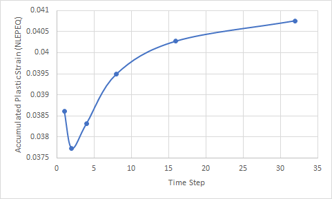
I have tried out time step of 1, 2, 4, 8, 16 and 32 and saw that it does affect the value of accumulated plastic strain (NLEPEQ). Attached below are the graph for each of the timestep used and results of NLEPEQ obtained, it is obviously not a flat line.
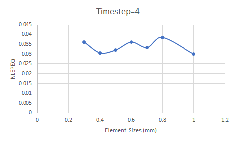
In this case, I believe that time increment also plays an important role in getting a successful mesh independence study. I have then proceeded to tried out minimum&initial timestep= 1, with different element sizes. Then, minimum&initial timestep=2, with different element sizes. Minimum&initial timestep=4 and lastly 8 with different element sizes. The value of NLEPEQ still do not converge with very fine mesh. Attached is example plot when minimum&initial timestep=4 is used. May I know what is your opinion on this?
Thanks.
November 10, 2021 at 12:24 pmAndrew_tan
SubscriberA follow up with the issue.
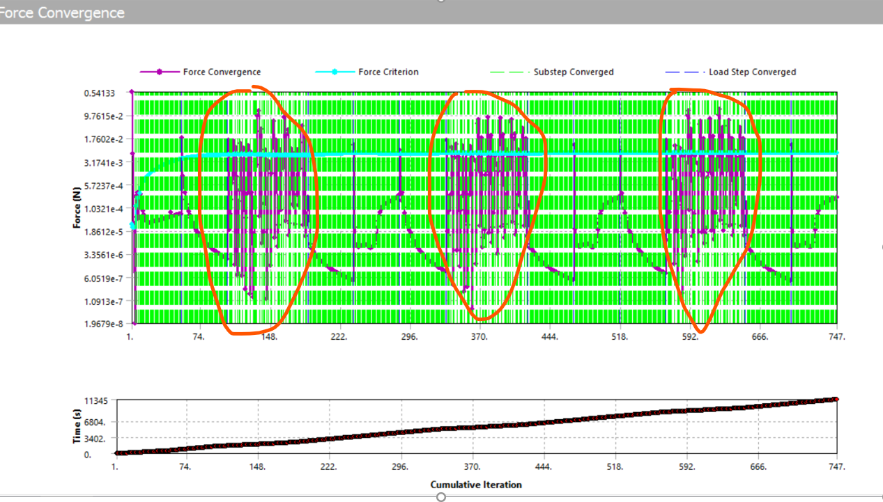
This is the force convergence plot when I am using very fine timestep of 48. I suspect there is error during three stages where I highlighted where the force is barely converged under the criterion. They are the stages where the temperature cycling ramps down. Does the force convergence at these 3 stages look fine to you? Or somewhere in the analysis could have been gone wrong.
November 10, 2021 at 3:55 pmpeteroznewman
SubscriberAs long as the model converges, you don't care if it needed extra iterations to converge. That is fine.
On the time step graph, higher number of steps means smaller time increments, so the time convergence is improving from 8, to 16 to 32. I would go with 32 for the element size study. Time step = 4 is not much better than Time step = 1.
Viewing 10 reply threads- The topic ‘Mesh independence Study for Non-Linear Static Structural Simulation’ is closed to new replies.
Innovation SpaceTrending discussionsTop Contributors-
4673
-
1565
-
1386
-
1236
-
1021
Top Rated Tags© 2025 Copyright ANSYS, Inc. All rights reserved.
Ansys does not support the usage of unauthorized Ansys software. Please visit www.ansys.com to obtain an official distribution.
-

