TAGGED: mesh, static-structural, strain
-
-
October 25, 2021 at 4:17 pm
adityap
SubscriberHello,
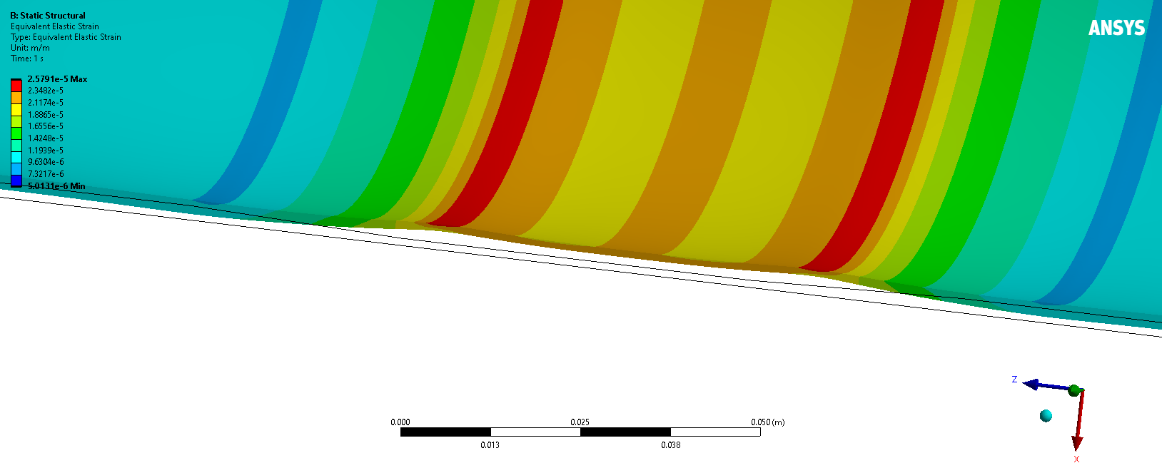
I am having issue with the strain data that I am getting from my static structural simulation. So, I have a cylinder with a thickness of 2 mm, but in the middle there is a 5 cm long flexure that is 1 mm thick. So I have added a transition between 2 mm to 1mm thick and vice versa. The goal of the study is to increase the localized strain so that I can get measurable strain data from strain gauges. Below is the picture of the side view of the geometry.
October 30, 2021 at 1:09 amSean Harvey
Ansys Employee
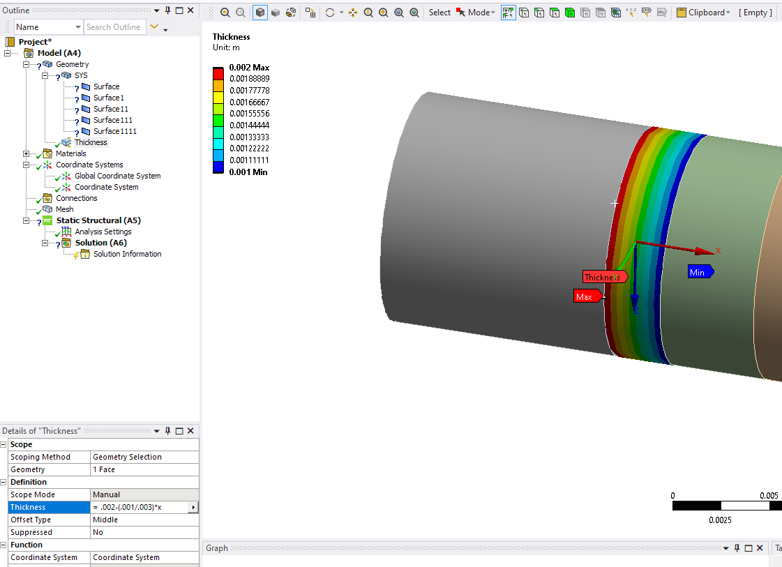
I'm interested to see if the bumps can be explained, so I will check that. If you wish to make as a shell, then you can model the tube out the outer diameter, insert a thickness object under geometry and then click on the right arrow and change to function and type an equation like I have done to change the thickness from .002 to .001. You need a coordinate system too for the equation. Repeat for both tapers. You then specify the offset to be bottom (in my case bottom, may be top depending on how the cylinder surface is created).

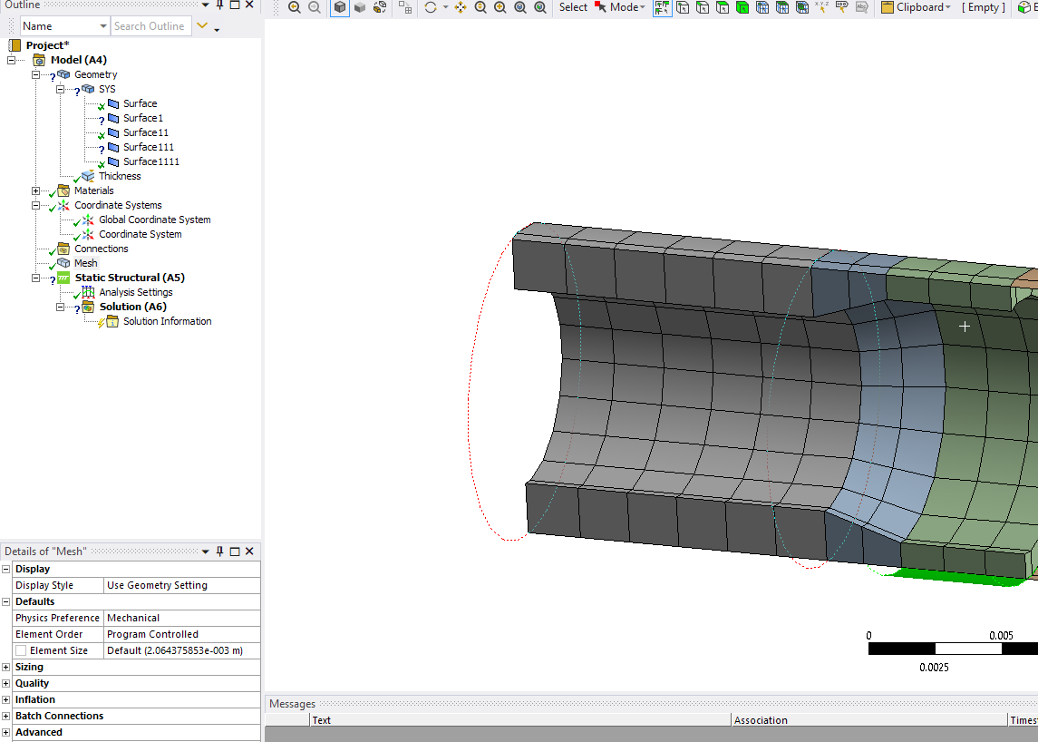
You then get something like the below which looks like solid, but is a shell with thickness effect. Ignore the right side as I did not do for other taper. Also, I started with too small a tube diameter so it looks so chunky, but you

Please try this and circle back with feedback or questions. Thanks!
Regards Sean
October 30, 2021 at 5:34 amSean Harvey
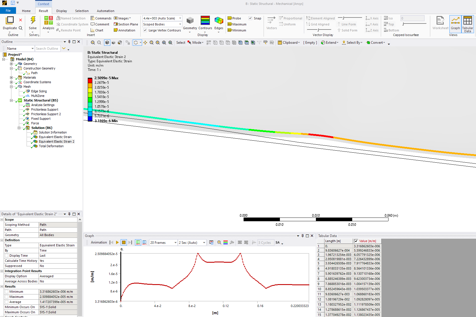
Ansys EmployeeHi @adityap So, now that I Iook in more detail, these spikes are expected. If you just take and put the tube in tension you will see this behavior Why?


If you were to do a free body diagram at the transition, you have what is below. The line of action of the force of the two sections has an offset. This results in a local moment being generated, and we can see that in the tube as it bends. Another way to think about it is to imagine the below is a a cross section flat slice of material with a taper. When we pull on the two ends, the specimen will try to rotate to establish equilibrium, and if it could rotate freely, the moment would be eliminated as the force vectors would align. But the structure can not simply rotate as if pinned , instead it has to elastically deform, and hence we end up with the development of an internal moment, and resulting stress peaks.
 I have seen this in practice in several occasions in my engineering practice.
A large thin wall tube with an indent (imagine you bang a tube with a hammer and dent it. Ignore any plastic deformation, pull on the tube and you will see local stress concentrations due to local bending. I have seen this proven with Ansys and small strain gauges. Some engineers at the time had a hard time believing the stress concentration was as high as we predicted with FEA, but then we go exact match with strain gauges.
Also, single overlap shear test specimens used in adhesive testing have the same offset effect and generate large moments that develop peel stress in the adhesive.
What you are seeing is not related to element behavior, but rather physical. Now with that said, you may see slight differences based on the formulation, and number of elements (mesh convergences) but do not expect to eliminate the spikes. Fundamental physics indicates they should be there. I hope this helps.
Regards Sean
October 31, 2021 at 7:09 pmadityap
SubscriberHi Sean,
Thank you for answering the question. It was my initial thought that there has to be an additional moment generated at that exact point that results in those spikes. I have one question in your free body diagram: Why are there tension forces or force in the axial direction? Is it because when we bend the tube, the bottom of the tube experiences tension?
Thank you again for your time.
Sincerely
Aditya
November 1, 2021 at 6:01 pmSean Harvey
Ansys EmployeeHello @adityap You are welcome. When we bend the tube, one side will experience tension straining, the other compression from the moment that is present due to the force applied. Does this clarify? Thanks.
Regards Sean
November 1, 2021 at 7:04 pmadityap
SubscriberIt makes sense. Thank you so much!
Sincerely
Aditya
November 1, 2021 at 10:45 pmSean Harvey
Ansys EmployeeHi @adityap Great. Glad to help.
Regards Sean
Viewing 6 reply threads- The topic ‘Weird strain spikes in a cylinder with varying thickness’ is closed to new replies.
Innovation SpaceTrending discussions- LPBF Simulation of dissimilar materials in ANSYS mechanical (Thermal Transient)
- Convergence error in modal analysis
- APDL, memory, solid
- Meaning of the error
- How to model a bimodular material in Mechanical
- Simulate a fan on the end of shaft
- Nonlinear load cases combinations
- Real Life Example of a non-symmetric eigenvalue problem
- How can the results of Pressures and Motions for all elements be obtained?
- Contact stiffness too big
Top Contributors-
4167
-
1487
-
1363
-
1194
-
1021
Top Rated Tags© 2025 Copyright ANSYS, Inc. All rights reserved.
Ansys does not support the usage of unauthorized Ansys software. Please visit www.ansys.com to obtain an official distribution.
-
The Ansys Learning Forum is a public forum. You are prohibited from providing (i) information that is confidential to You, your employer, or any third party, (ii) Personal Data or individually identifiable health information, (iii) any information that is U.S. Government Classified, Controlled Unclassified Information, International Traffic in Arms Regulators (ITAR) or Export Administration Regulators (EAR) controlled or otherwise have been determined by the United States Government or by a foreign government to require protection against unauthorized disclosure for reasons of national security, or (iv) topics or information restricted by the People's Republic of China data protection and privacy laws.


