-
-
October 24, 2021 at 8:34 pm
nurionur
SubscriberHello,
I am trying to simulate Impedance Tube and obtain absorption coefficient.
I have three body including 2 acoustic body(air) and 1 structural (absorber).
I define surface velocity as 0.01 mm/s on port and it is also radiation boundary.
I define rigid wall on the other side of tube.
I define fluid solid interface automatically.
I define displacement 0 on both direction for absorber.
I check a lot of article and tutorial but I can not understand what is my mistake.
I need someone guidance. Please help. Thank you.
October 25, 2021 at 6:43 amErKo
Ansys EmployeeHi
You will not be able to predict for a solid 3D structure since the absorption is a thermal and viscous effect that is caused say for instance by the coupling of acoustic and elastic waves in porous material so quite complex - you can predict this though to certain extents if you use a an equivalent model - so know the porosity, fluid resistivity,....,for JCA or fluid resistivity for Delany-Bazley equivalent model. See the help manual for a range of validity for these models which assume a rigid skeleton (JCA), but also Bazley can be used for very soft mineral wool type of absorbers say like those of rockwool type found in acoustic applications. So they can be used to account for absorption is foam like material to a certain extent
To assign these properties go to engineering data:

Hope this helps
Erik
October 25, 2021 at 7:47 amnurionur
SubscriberHello Erik Thanks for answer.
I tried JCA and gave these values that are from one of ansys tutorial. But it doesn─▒'t work. I really can not understand why the values are 0. I saw some article to do these simulation and obtained similar values with their tests. Do you have any experience about it? Do you think that my model is correct, should I add another boundary condition?
Thanks

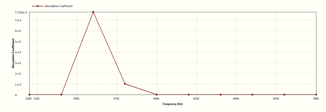
October 25, 2021 at 8:25 amErKo
Ansys Employee
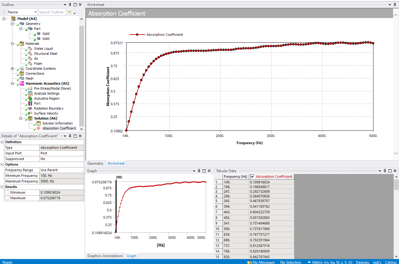
See the example below - in an impedance tube there is no air behind the sampe normally so take that away, and no need to assign fixed displacement since it is an acoustic element and no need for coupling since it is pure acoustics (the Bazley is pure acoustics). Have in mind we are using the latest release 20201 R2 with harmonic acoustics (I do not use and can not help with the act extension since this is not native)
All the best
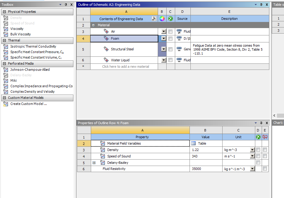
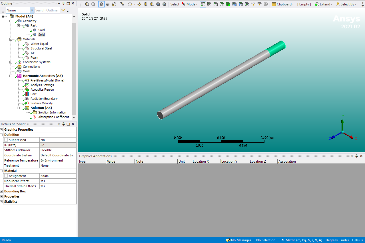
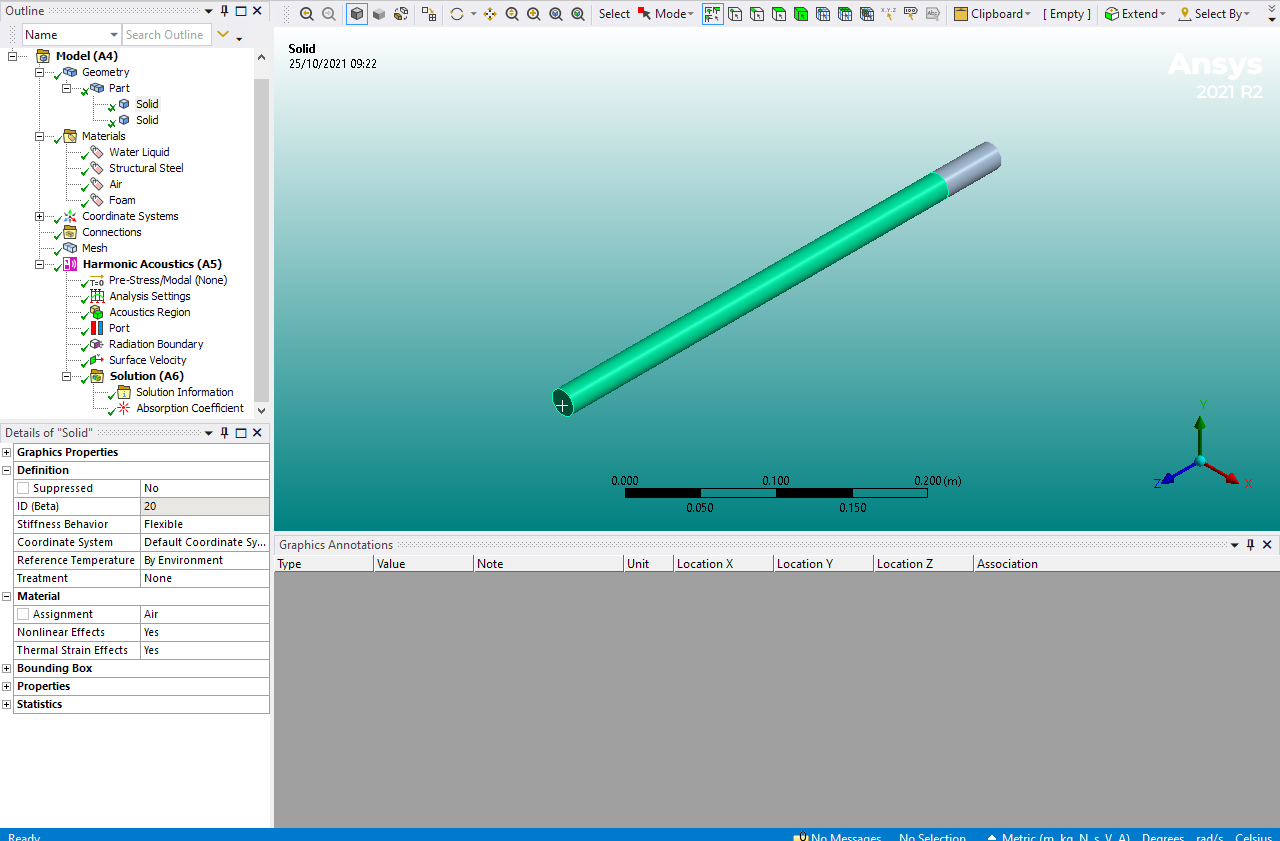
Erik
October 25, 2021 at 10:20 amnurionur
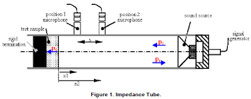
SubscriberHi Erik Now I obtain more meaningful results as similar with yours. Thank you so much. I dropout boundary conditions as you said and it made sense in fully acoustic case. But What happened if the material is rigid body. I guess, I should use JCA, displacement and rigid wall boundary conditions. As you see in the figure, there is rigid wall and zero displacement. Can you give advise about that? or Do you have any document to guide?
 I really appreciated up to this point. Thank you
October 25, 2021 at 10:38 amErKo
Ansys Employee
So just use as before - the sample example I showed is modeling an impedance tube with a sample in it, so just as you show.
The test sample is either JCA or Delany-Bazley, and that is it.
have in mind that we only need/have acoustic elements so the degree of freedom is only pressure so no need for displacements.
For rigid wall in acoustics:
Where ever we do not prescribe boundary conditions on the acoustic outer domain (so all outer faces) they will be acoustically hard (so acoustic velocity is zero there), so these are natural boundary conditions.
(If you still want to do it and define them, which we do not have to as I said above, there is an acoustic boundary condition called rigid wall).
So that rigid body in the back does not have to be modelled since it just provides a rigid wall at the back of the sample which we have if we do not assign any boundary conditions there as mentioned above, or if we assign a rigid wall at the back of the sample.
Thank you
Erik
October 25, 2021 at 11:08 amnurionur
Subscriber
I got it.
But elastic behaviour also affect absorption coefficient, doesn't it? When I add isotropic material properties such as modulus elasticity and poisson ratio for the same material, both results are exactly same. In order to consider elastic behaviour for absorption coefficient, I think we should assign FOAM as a physical body, shouldnt we?
October 25, 2021 at 11:16 amErKo
Ansys EmployeeHi
As we said the JCA and Delany-Bazley are acoustic models that (predict the sound absorption due to thermal viscous effects (the skeleton is rigid) - see theory manual for more info.
An elastic structure in ansys cannot account for any acoustic absorption so that can not be accounted for in wb mechanical. An elastic body in acoustics is e.g., useful for doing vibroacoustics so say a vibrating elastic steel structure might generate sound in the surrounding acoustic air domain say, but again it can not be used to absorb any sound/acoustic energy (it can not model that effect).
All the best
October 25, 2021 at 12:26 pmnurionur
SubscriberOkay. As far as I understood, in my case, Ansys wb mechanical only consider perforated media properties. For example, ─░f I changed my design that has more porous structure, ansys mechanical doesn't account this design situation unless I change porosity , right?
My aim is to include both physical property affects (elasticity), design property (porous, thickness etc ) and perforated media properties (porous, resistivity). Do you have any advice to do this kind of analysis on Ansys.
Thank you
October 25, 2021 at 1:02 pmErKo
Ansys EmployeeHi
So only when we use JCA and Delany-Bazley perforated acoustic models (se engineering data, and theory manual) on an acoustic domain/body will it give some contribution and an acoustic absorption in these type of tests.
In ansys, elastic materials/structure do not account and contribute to the acoustic absorption so elastic structural bodies in a model will not affect the acoustic absorption (thus you can not do what you want since it does not account for that) - only the acoustic bodies that are assigned JCA or Delany-Bazley properties as I showed in the previous example will.
All the best
Erik
October 26, 2021 at 6:10 amnurionur
Subscriber
What about Sound Transmission Loss?
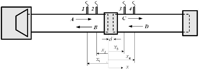
If I tried simulation of Sound Transmission Loss, it would be another concepts as below. In this case, I think displacement, acoustic and physical region should be used. Do you have an suggestion about boundary condition or material property(such as JCA). Can you share an example for it? It should be different from absorption concepts.
Thank you.
October 26, 2021 at 7:12 amErKo
Ansys EmployeeHi
I do not have an example of this. Also have in mind that ansys employees are not allowed to share any models .
All the material properties is something a user needs to input, so up to the user.
As we said now the JCA Perforated material models are pure acoustics and have only pressure dof so no need to restrain them thus- if it is glued say to a steel plate say then you can you include a structure but then the steel plate needs to have some restrains if it is has it in reality of course, since it has translational degrees of freedom. Again have in mind what we said many times, that only the perforated material model (e.g.,Delany-Bazley) will provide some absorption of acoustic energy, the steel plate can not do that (as we said it can not absorb acoustic energy). Of course it can reflect acoustic energy since it provides a different impedance to the air thus reflecting back energy acting like an acoustic barrier, but it can not absorb acoustic energy (say converting it to heat or viscous losses like perforated model does - this is inbuilt in the perforated material model formulation - see help manual for more info).
All the best
Erik
November 24, 2021 at 8:13 pmkasparek1
SubscriberHello Erik,
I am trying to do similar analysis of impedance tube to determine absorption coefficient of some specimen. I tried to replicate your settings but I don't see exactly how you used boundary conditions. I set Port on input face and Radiation Boundary at the same face. I also put loading (acoustic pressure) to the same face. Is it correct?
The problem is that when I try to evaluate absorption coefficient on a Port (input face), there is an error saying: "The input power at the driven port is equal to zero". Could you please tell me what could cause this problem? Or could you please tell me if my BCs are different than yours?
Thanks in advance
Have a nice day
November 25, 2021 at 7:22 amNovember 25, 2021 at 9:30 amkasparek1
SubscriberHi I chose Delany - Bazley and input fluid resistivity value. I tried to set Acoustic velocity instead of pressure, but unfortunately the problem still occurs.
Do you know what else could cause the problem? I use student version of wb 2021 R2.
Thank you
Have a nice day
November 29, 2022 at 3:14 pmnitishkat
SubscriberWhy can't constant pressure (eg 1 Pa) act as a stimulus?
November 30, 2022 at 7:58 amTayyib Can Bahadır
SubscriberWhen i add port i have 2 options. First one is porous material and second one is rigid object. First i choosed rigid object and it worked and gave me a results like Erik's. There is a huge numbers of coifficent it didn't reduce just increased. After that i selected porous metarial and i had an error it said 'The input power at the driven port is equal to zero. Please check the port definitions.'
So is this analyze true or not?
I think i did a mistake but i couldn't realize it.
Viewing 16 reply threads- The topic ‘What is the reason of Absorbtion Coefficient too small or zero on Impedance Tube Simulation?’ is closed to new replies.
Innovation SpaceTrending discussions- LPBF Simulation of dissimilar materials in ANSYS mechanical (Thermal Transient)
- Simulate a fan on the end of shaft
- Nonlinear load cases combinations
- Real Life Example of a non-symmetric eigenvalue problem
- How can the results of Pressures and Motions for all elements be obtained?
- Contact stiffness too big
- Test post on Forum – LLM response – SC
- 13-Node Pyramid Element Shape Function
- Element Birth and Death
- Python-Script to Export all Children of a Solution Tree
Top Contributors-
4512
-
1494
-
1386
-
1209
-
1021
Top Rated Tags© 2025 Copyright ANSYS, Inc. All rights reserved.
Ansys does not support the usage of unauthorized Ansys software. Please visit www.ansys.com to obtain an official distribution.
-


Ansys Assistant

Welcome to Ansys Assistant!
An AI-based virtual assistant for active Ansys Academic Customers. Please login using your university issued email address.
Hey there, you are quite inquisitive! You have hit your hourly question limit. Please retry after '10' minutes. For questions, please reach out to ansyslearn@ansys.com.
RETRY


