TAGGED: 2D, ansys-maxwell-electronics, maxwell, modeling, structure
-
-
October 22, 2021 at 7:35 am
Francoo
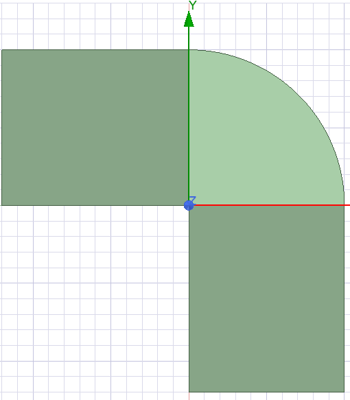
SubscriberThe structure consists of a corner region with radial lamination and also several straight parts with continual lamination. How could I define the lamination direction? Or the coordinates?
October 22, 2021 at 8:05 amFrancoo
SubscriberIt is actually a radially laminated core, made of amorphous or nanocrystalline material.
October 28, 2021 at 1:45 amNKC
Forum Moderator
For the radial part Define a local coordinate system, make this the reference co-ordinate system under this object attributes
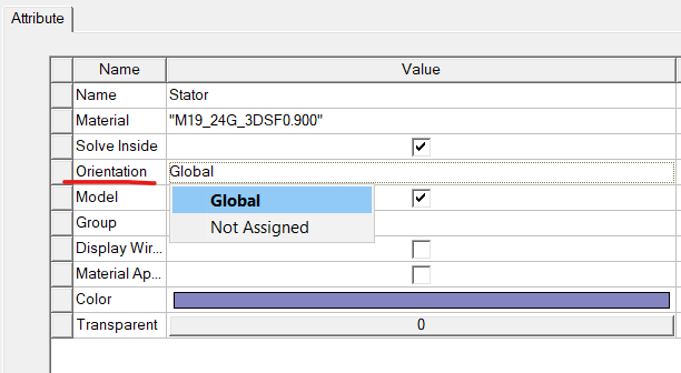 After that, while assigning the material properties on the material definition window.
Change the Material coordinate system as Cylindrical and stacking direction as V(1)
Note that V(1), V(2), V(3) corresponds to X,Y,Z directions of stacking in Cartesian coordinate system and R, Phi, Z in a cylindrical coordinate system.
So, V(1) refers to Radial direction here.
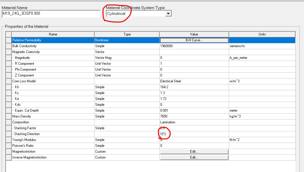
An for the straight parts just define the stacking direction with global coordinates, cartesian and V(1)/V(2)/V(3) as per the direction.
Regards Navya
October 28, 2021 at 3:25 amFrancoo
SubscriberHi @nchode Thank you very much for your information! After the settings are done, some issues still occur. Could you please kindly help me indentify the problem?
The ribbon laminated core has a magnetic property similar to toroidal cores, and the flux density distribution in the corner region is as shown below, found in a research article:
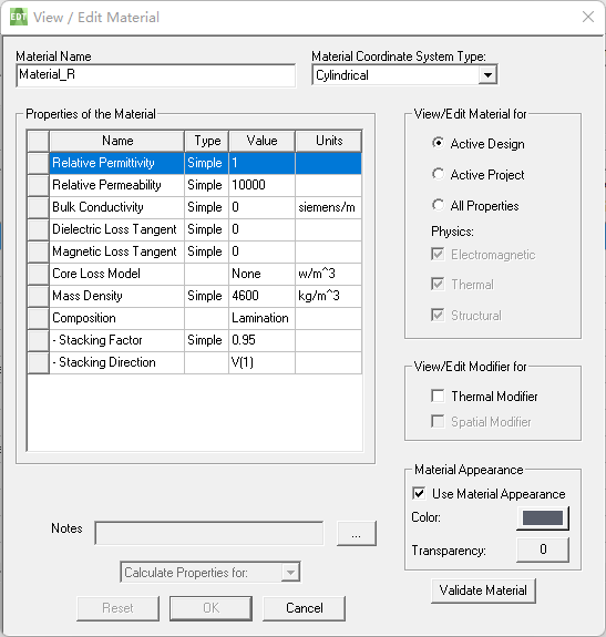
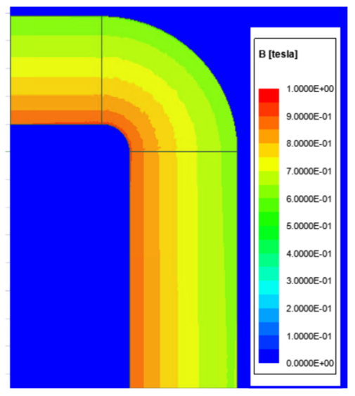 I created a 3D model to simulate this effect. The first option is to set the lamination of the material. Following your instructions, the radial parts and the straight parts are separately applied to different materials with corresponding lamination settings. But the results seem not correct, which is depicted below as well as the material setting specified for the radial material (similar for the straight parts):

 Therefore, I was wondering maybe setting anisotropy of the permeability is a better choice. Yet, the ANSYS Maxwell fails to converge this time:
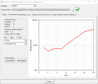 My settings are arranged as below:
All the models are created under Cartesian coordinates.
The material properties of the radial, horizontal and vertical parts are shown respectively:
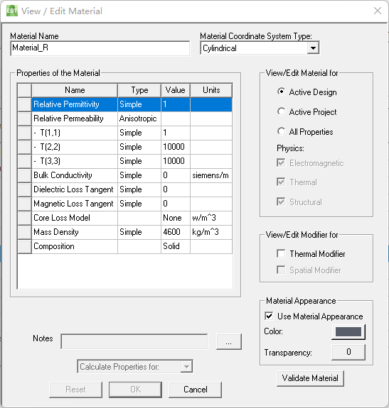
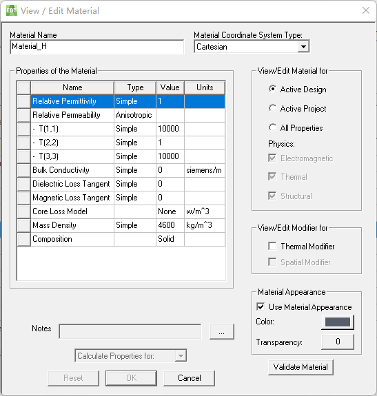
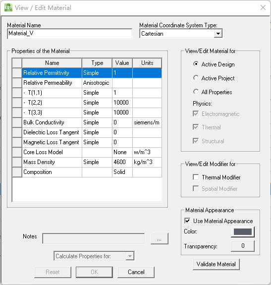
BTW, The radial objects has been bonded to the relative coordinates system whose direction of Z axis is the same with the globel CS. The simulation is conducted in ANSYS Electronics Desktop 2021 R1.
Thank you so much for helping me!
October 28, 2021 at 7:23 amFrancoo
SubscriberThe problem has been fixed. The core of the solution is you need to bond the radial part with a specific relative coordinate system, so that its z axis has correct meaning.
Viewing 4 reply threads- The topic ‘How to model the lamination core structure that contains corner region and straight region?’ is closed to new replies.
Innovation SpaceTrending discussionsTop Contributors-
4703
-
1565
-
1386
-
1242
-
1021
Top Rated Tags© 2025 Copyright ANSYS, Inc. All rights reserved.
Ansys does not support the usage of unauthorized Ansys software. Please visit www.ansys.com to obtain an official distribution.
-
The Ansys Learning Forum is a public forum. You are prohibited from providing (i) information that is confidential to You, your employer, or any third party, (ii) Personal Data or individually identifiable health information, (iii) any information that is U.S. Government Classified, Controlled Unclassified Information, International Traffic in Arms Regulators (ITAR) or Export Administration Regulators (EAR) controlled or otherwise have been determined by the United States Government or by a foreign government to require protection against unauthorized disclosure for reasons of national security, or (iv) topics or information restricted by the People's Republic of China data protection and privacy laws.

