TAGGED: ansys-fluent, boundary-conditions, cfd, fluids, heat-transfer
-
-
October 11, 2021 at 8:47 am
ss_stardust
SubscriberHi,
I wanted to ask how the heat flux applied at the wall of a pipe completely filled with porous media is divided into fluid and solid fractions of the porous media by ANSYS FLUENT . Exactly what fraction of a constant heat flux applied at the walls will be given to solid and fluid energy equations and how this bifurcation of flux takes place? Also, where this heat flux is required to be input, at the solid wall created by copied cells or at the wall adjacent to fluid domain?
Thanks in advance.
October 13, 2021 at 9:01 pmKarthik Remella
AdministratorHello Is this an internal or external wall that you wish to apply the boundary condition to? Could you please provide a simple sketch so I can understand your question better?
Karthik
October 14, 2021 at 5:26 amss_stardust
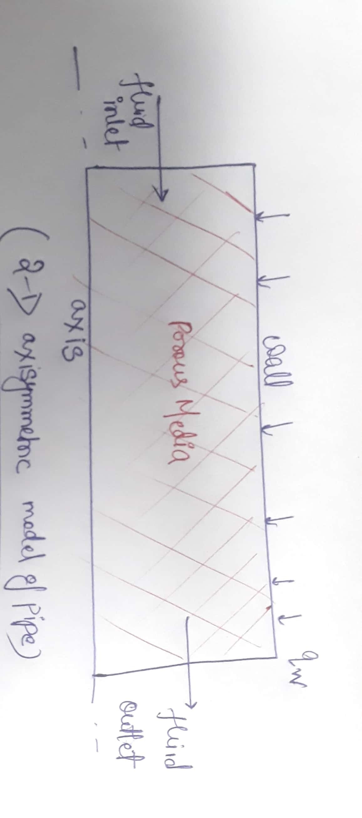
SubscriberHi Please refer to the image attached. I want to know how the heat flux at the wall is being bifurcated between solid and fluid zones of the porous medium in contact with the wall. I am having trouble understanding how LTNE model of FLUENT works at the boundaries and interfaces . What equations does it solve there? I have referred to User and theory guide, however nothing much regarding is given there.

October 18, 2021 at 6:43 pmOctober 21, 2021 at 2:39 pmss_stardust
SubscriberHi Can someone please try to answer and clear the doubt ?
October 25, 2021 at 2:28 pmKarthik Remella
AdministratorHello Apologies for the delayed response to this one. To do what you want, it is best to start with a non-conformal mesh (without share topology). Once you load the mesh into Ansys Fluent, you will need to carefully identify the face zones corresponding to the Fluid, the spatially coincident solid, and the adjacent solid. To obtain the three zones, you may need some mesh manipulation operations (these can be found as TUIs under /mesh/modify-zones/ . Once you have these three faces, you should be able to 'Manually' create mesh interfaces. These interfaces should help you obtain the final set of conditions you wish to model. I'd suggest that you take a simple test problem (simple pipe flow with a solid wall) and test this method on this. Once you are confident that it is working as intended, then please feel free to employ this on your problem. Please note that it would require carefully identifying the face zones. Please use the 'Adjacency' panel for this.
I hope this helps.
Karthik
October 30, 2021 at 5:45 pmss_stardust
SubscriberHi Thanks for reply.
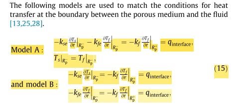
This doesn't seem to work. Can you please explain what equations are solved at interfaces as in case of porous media, continuity of velocity, shear stress and heat flux is required. There are a number of models available in literature to have heat flux conservation. Which model does fluent follow? To make my question more clear, please see the attached picture which considers two models. Can you please mention what model is implemented in fluent?
Thanks in advance.

November 9, 2021 at 11:08 amss_stardust
SubscriberHi Please look into the problem. FLUENT manual has very limited explanation about LTNE model and no resources are available at either forum or customer portal.
November 9, 2021 at 11:13 amss_stardust
SubscriberI did applied your solution to manually create the interfaces but it just creates empty surfaces and gives the error as :
"
Warning: surface-integrate: empty surfaceNote: zone-surface: cannot create surface from sliding interface zone.
Creating empty surface.
"
November 11, 2021 at 10:14 amss_stardust
Subscriber
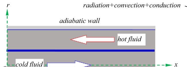
As per your solution for creating coupling, when there are multiple parts as in case of axisymmetric model of double pipe heat exchanger with a wall separating them, what kind of mesh connectivity should be used?
November 11, 2021 at 1:24 pmKarthik Remella
AdministratorHello I would make sure that you have similar mesh sizes on both sides of your wall. If you are using a conformal mesh, that would be the best. If you are working with a non-conformal mesh, then you might have to pay attention to ensure similar mesh sizes on both sides.
Karthik
November 11, 2021 at 1:56 pmss_stardust
SubscriberThanks for the reply.
I have referenced to Solution no. 2056744 given on customer portal. They have mentioned that if we want to couple all three zones at walls, non-conformal meshing is recommended. So, I want to implement that in my model. However, I am not getting how to make connections between different zones. Please help in doing so. My model is 2-D axisymmetric.
December 4, 2021 at 8:03 amss_stardust
SubscriberHi Anyone there to help me understand the doubt mentioned above? Please help as I am stuck at this for a really long time.
Viewing 12 reply threads- The topic ‘heat flux at interface of porous media and wall in LTNE model’ is closed to new replies.
Innovation SpaceTrending discussionsTop Contributors-
4929
-
1638
-
1386
-
1242
-
1021
Top Rated Tags© 2026 Copyright ANSYS, Inc. All rights reserved.
Ansys does not support the usage of unauthorized Ansys software. Please visit www.ansys.com to obtain an official distribution.
-


