-
-
October 3, 2021 at 8:37 pm
AMFCB
SubscriberIn a non linear static analysis in Ansys Mechanical, I have a simple fiber reinforced composite (hexagonal pattern unit cell with circular fibers and surrounding matrix). When I apply a displacement "d" on the face nodes of the model, I am getting different ultimate stress and ultimate strain values for different values of "d". Shouldn’t the ultimate stress and strain values be almost constant regardless of what the applied displacement or strain is? (I am calculating the stress as the total force on the nodes of the face divided by the area of the face). I am using the maximum stress failure criteria with material property degradation. I also have constant time stepping (100 substeps)
October 4, 2021 at 1:17 ampeteroznewman
SubscriberIf the materials are in the linear elastic range with a first value of displacement d, and you double that to a value of 2d, which is still in the linear elastic range, then the stress and the strain should double.
October 4, 2021 at 4:38 amAMFCB
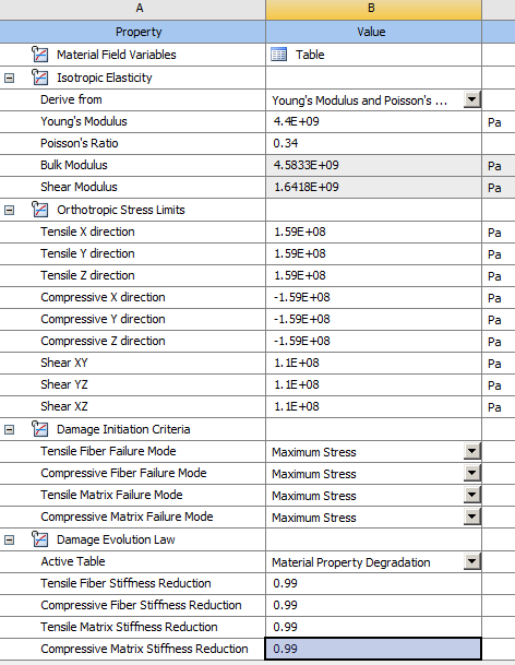
SubscriberThank you for your quick response. My materials are not in the linear elastic range. For instance for a fiber reinforced composite where the failure strain of the fiber is 1.8%, applying two different displacement values of "d" and "2d", both greater than 1.8% strain, gives 2 different failure strains. For example, I have attached an image here of the material properties I use for a simple cube model that is made entirely of an isotropic epoxy. In the elastic range, like you said, the analysis is linear and I get good agreement with the stiffness value.
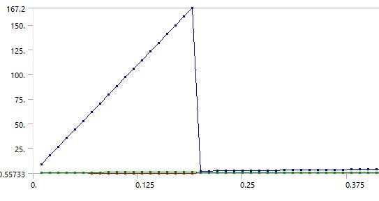
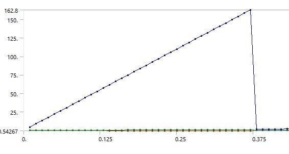
For the first case, I am just using the isotropic elasticity property (damage initiation, evolution and orthotropic stress limits are not used in the first case), and the stiffness matches the expected result of 4.4 GPa. Boundary conditions: ux_left=0, uy_back=0, uz_bottom=0, ux_right = 10% strain. For the second case, I am using the damage model with the stress limits. In the second case, an applied strain of 10% gives a failure stress of 162.8 MPa and a failure strain of 3.7%, whereas an applied strain of 20% gives a failure stress of 167.2 MPa and a failure strain of 3.8%. This is the case with an isotropic material, the discrepancies are higher with a composite. (I chose the strain sufficiently higher than the failure strain of the epoxy). The two plots below show the stresses at each time step (time on the x-axis).
I am not sure why this is the case, because even if not an exact value, the failure stress and strain shouldn't vary irrespective of the applied load magnitude. What am I missing here?


Viewing 2 reply threads- The topic ‘Nonlinear static analysis with failure initiation and evolution’ is closed to new replies.
Innovation SpaceTrending discussionsTop Contributors-
4678
-
1565
-
1386
-
1242
-
1021
Top Rated Tags© 2025 Copyright ANSYS, Inc. All rights reserved.
Ansys does not support the usage of unauthorized Ansys software. Please visit www.ansys.com to obtain an official distribution.
-


Ansys Assistant

Welcome to Ansys Assistant!
An AI-based virtual assistant for active Ansys Academic Customers. Please login using your university issued email address.
Hey there, you are quite inquisitive! You have hit your hourly question limit. Please retry after '10' minutes. For questions, please reach out to ansyslearn@ansys.com.
RETRY


