

-
-
September 30, 2021 at 1:26 pm
niazulkhan
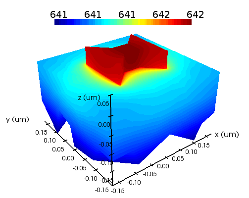
SubscriberAttached is the heat profile from the support example of Lumerical at this link: https://support.lumerical.com/hc/en-us/articles/360041686234-Photothermal-heating-in-plasmonic-nanostructures
I have two questions:
- The example says its the heat profile for an array of diabolo antenna of 0.34 um pitch. However, the simulation region in both the FDTD and Heat solver simulation region just contain one antenna. I am wondering what the simulator understands that it is an array.
- The image only shows the heat profile from -0.17 um to +0.17 for both x- and y-axis. I wanted to look at the heat profile beyond. Therefore, I was trying to extend the x- and y-region, but could not find a option. Any help?
September 30, 2021 at 5:13 pmGuilin Sun
Ansys EmployeeThe first question is very interesting, as in experiment we see a physical array, but inside the simulation region there is only one unit. The array (infinitely repeat) in simulation is guaranteed by applying the proper periodic BCs. In this case, since the source and the structure have symmetry, so the boundaries are chosen symmetric and anti-symmetric:
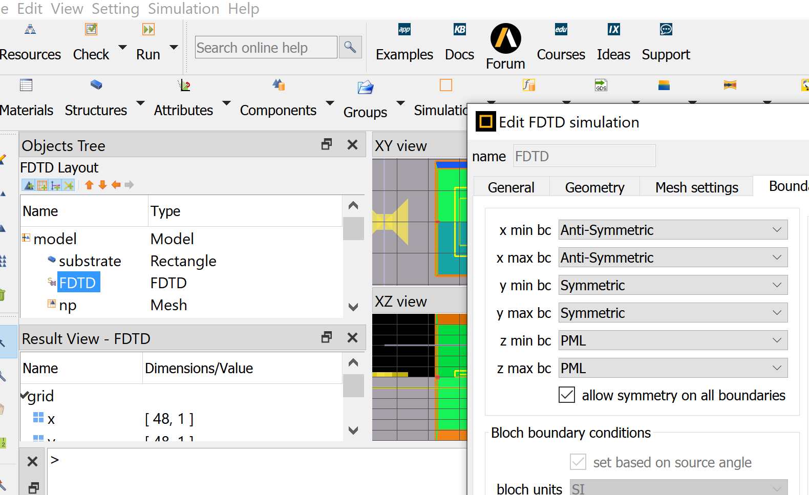 more information can be found here: Symmetric and anti-symmetric BCs in FDTD and MODE
To show results for more periods, please refer this example:Silicon solar cell with TiO2 pyramid array
you can borrow its script in the analysis group.
September 30, 2021 at 10:05 pmSubscriberHi, Thanks a lot for explaining about the issue of array. However, the array has a pitch of 0.34 um, so I guess that's the reason that in the FDTD solver the simulation region is 0.34 um x 0.34 um. But I would like study the effect of gap between the array elements, and want to find the maximum gap for which the the array effects diminish i.e. the antenna acts like a single antenna (as they have a separate file in the example link: diabolo_single.fsp with PML BC). My question is: how I can do this using the diabolo_array.fsp file? Will that make sense if I continue to increase the dimension of the FDTD region of the file diabolo_array.fsp keeping the same BC (symmetric and anti-symmetric). In fact I found that at pitch=1.36 um, the temperature rise is approximately close to found by the diabolo_single.fsp file. However, the temperature for the diabolo_array.fsp seems the same everywhere (still array effect??) where for the diabolo_single.fsp file, the temperature profile has high variation inside the simulation region which seems correct to me.
I would appreciate if you could explain this, thanks a lot.
September 30, 2021 at 11:49 pmAnsys EmployeePeriodicity is determined by the period you set in FDTD. It is periodic characteristics that determines the final effect. The diabolo size can also change if you want. You may use duty cycle to quantify the gap, which is used in grating design.
October 1, 2021 at 3:45 amSubscriberThanks, but I would not change the diabolo size, I would like to see at what pitch/gap the array is not an array anymore, i.e. each antenna is isolated and is not affected by the neighboring antenna.
October 1, 2021 at 4:42 pmAnsys EmployeeYes, changing the period will give you the result you desire, if you want to quantify an arry.
If you want to quantify a single, isolated diabolo with given size, there will be no pitch/gap parameters, since they are used to quantify periodic structures. When more than one diapolo works together, coherence happens since they interact each other, meaning the scattered EM waves will interact with each other.
In summary, if you want to investigate an array effect with different pitch/period or gap, simply change the period, and you are simulating single ONE unit of the array. When periodic BCs are used, we assume this array is mathematically infinite. While in practice the array is limited, the result will be about the same as long as there are sufficient number of diabolo. If you have only a few, say 3by3, you will need simulate them as a whole, with PML BCs.
Viewing 5 reply threads- The topic ‘Photothermal heating in plasmonic nanostructures’ is closed to new replies.
Ansys Innovation Space Trending discussions
 Top Contributors
-
peteroznewman
 3572
3572 -
scabo
 1193
1193 -
Dennis Chen
 1076
1076 -
javat33489
 1063
1063 -
Shyam Prasad V Atri
952
Top Rated Tags
© 2025 Copyright ANSYS, Inc. All rights reserved.
Ansys does not support the usage of unauthorized Ansys software. Please visit www.ansys.com to obtain an official distribution.
-


The Ansys Learning Forum is a public forum. You are prohibited from providing (i) information that is confidential to You, your employer, or any third party, (ii) Personal Data or individually identifiable health information, (iii) any information that is U.S. Government Classified, Controlled Unclassified Information, International Traffic in Arms Regulators (ITAR) or Export Administration Regulators (EAR) controlled or otherwise have been determined by the United States Government or by a foreign government to require protection against unauthorized disclosure for reasons of national security, or (iv) topics or information restricted by the People's Republic of China data protection and privacy laws.


