-
-
September 28, 2021 at 9:14 am
pietro_lopo
SubscriberHi everyone, i have to do a verification on a beam wich is sollecitated with static and dynamic forces.
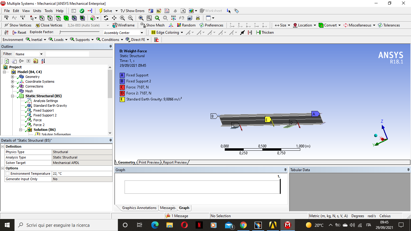
The static force is the weight force applicated by an another structure linked to the beam, in the z-direction.
While the dynamic forces are forces that change in time. The magnitude is always the same but the direction follows a circular trajectory. So the direction changes from longitudinal to transversal.
How can I define this kind of forces? I also need to do a fatigue analysis, but in the fatigue tool i can't choose the force that i want to change in time. (the weight force is always the same).
How can i solve this problem?
Thank you and best regards.
September 28, 2021 at 11:23 ampeteroznewman
SubscriberThe word "dynamic" used in a conversation about simulation implies that inertia forces are significant.
What is the rotational speed of the rotating force? If it is slow compared with the first natural frequency of the structure, then this rotating force would be considered "quasi-static".
If that is the case, then to do a fatigue analysis, choose the angle of the force that generates the largest stress and use only that force in the model. Do not include the weight force because there are no cycles of fatigue caused by that weight. Solve the model with just the weight and use the stress from that solution as a mean offset to the amplitude of the cyclic rotating force.
September 28, 2021 at 12:11 pmpietro_lopo
SubscriberOk so, the force's rotational speed Is like 250 RPM.
Should i calculate the first natural frequency of the structure without forces or including the weight force?
September 28, 2021 at 3:02 pmpietro_lopo
Subscriberok so, my rotation frequency is 4,16 Hz and the first natural frequency of my system is about 28 Hz. Now, assuming that i am in a quasi-static situation how do i do what were you suggesting me? "Solve the model with just the weight and use the stress from that solution as a mean offset to the amplitude of the cyclic rotating force."
I resolved the system using only the weight-force but i don't know how to export this data in a new model. Sorry for my insistence, and i want to thank you again for the help!
September 29, 2021 at 1:25 ampeteroznewman
SubscriberFind the direction of the rotating force that produces the maximum stress in the structure without gravity. Maybe it is obvious. For example, in the case of a force at the end of a cantilever beam, the maximum stress is when the force is in the direction of the thin dimension.
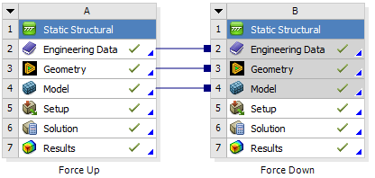
Duplicate the Static Structural analysis. I named these Force Up and Force Down.
 In each system, use the supports you need, and Standard Earth Gravity, and the rotating force. In the first system the force is defined with components and is a positive value to push up and in the second system the force has a negative value to push down. Insert a Fatigue Tool in each system. In each system make the Loading Type Zero-Based.
Right click on the Model branch and insert a Fatigue Combination.
 In the Worksheet, add each force direction.
 Insert a Damage result into the Fatigue Combination.
The Damage result is computed from cycling between the stress state of the force going up and the force going down, including the effect of the weight of the structure.
Read the post below by who can correct me if I said something wrong or corroborate if I said it right.
/forum/discussion/23024/fatigue-combined-loads
September 29, 2021 at 7:56 ampietro_lopo
SubscriberOk, but... i'll explain better my case.
I split it in 2 cases:
CASE 1: Gravity Force + Weight force given by the machine linked to the beam ( forces D and C)
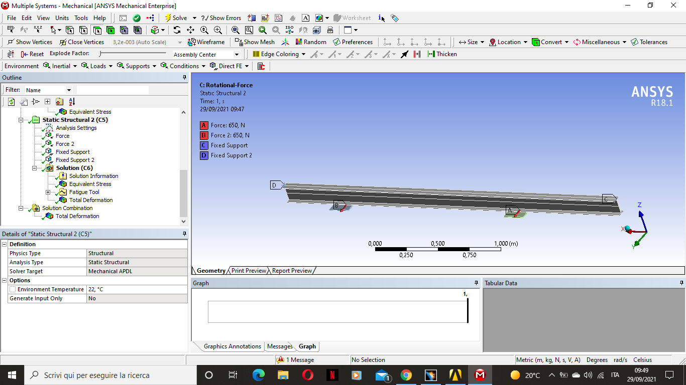
 CASE 2: Rotating force (i considered only the component in the Y-axis direction, which is the most dangerous one, and I inserted in this case the fatigue tool)
 Now, if I use the solution combination tool, and insert in this the fatigue tool, will it be a correct model?
The forces in the 1st case (forces C and D) are the static one, while the forces in the 2nd case (A and B) are the rotating one and i inserted only the y-component, and in the Fatigue Tool i used the fully reversed cycle to "simulate" a sort of rotation.
What do you think?
Thank you by the way, you have been very helpful!
September 29, 2021 at 9:12 pmpeteroznewman
SubscriberI suggest you delete the two downward static forces and add two point mass elements scoped to the same two faces. A 724.7 kg mass generates one of those forces with a gravity load.
Now you only have the rotating forces acting in the Y direction. If they are always synchronous, then things are simple. Take system B with gravity, the two point masses and the two rotating forces that have a positive magnitude in the Y direction. Duplicate system B to create system C. Edit the two rotating forces and use a negative sign. These two systems represent the two states of stress that the structure oscillates between.
Insert the Fatigue Combination to sum the damage from these two systems.
September 30, 2021 at 12:04 ampietro_lopo
SubscriberAwesome! That's brilliant! I didn't know the point mass function!
Anyway in my versione of Ansys there isn't the fatigue combination tool so i'll try with the solution combination.
Thank you very much for the help, from Pietro to Pietro!
September 30, 2021 at 12:56 ampeteroznewman
SubscriberI think the Solution Combination is going to add the stress from these two conditions. That will result in double the gravity while the Y direction forces cancel each other out. You can get the Damage from each Fatigue Tool and add them together yourself.
Viewing 8 reply threads- The topic ‘Static and Dynamic Forces, how to configure?’ is closed to new replies.
Innovation SpaceTrending discussionsTop Contributors-
4633
-
1535
-
1386
-
1225
-
1021
Top Rated Tags© 2025 Copyright ANSYS, Inc. All rights reserved.
Ansys does not support the usage of unauthorized Ansys software. Please visit www.ansys.com to obtain an official distribution.
-


Ansys Assistant

Welcome to Ansys Assistant!
An AI-based virtual assistant for active Ansys Academic Customers. Please login using your university issued email address.
Hey there, you are quite inquisitive! You have hit your hourly question limit. Please retry after '10' minutes. For questions, please reach out to ansyslearn@ansys.com.
RETRY


