-
-
September 25, 2021 at 9:18 pm
nlm54
SubscriberHi,
I am trying to perform a thermal analysis simulation of an imported board from Altium Designer and its 3D component bodies, but when I simulate the board it says that the thermal results of the simulation of the board should be 2062 degrees celsius. I know that is completely incorrect because the results during experimentation are 113 degrees celsius. I am only using one element to dissipate heat just to get the simulation working, but have been unable to correct this issue
September 28, 2021 at 4:47 amSeptember 28, 2021 at 3:05 pmnlm54
Subscriber
I am not sure what you mean by try reassigning material to the board after importing it to Icepak?
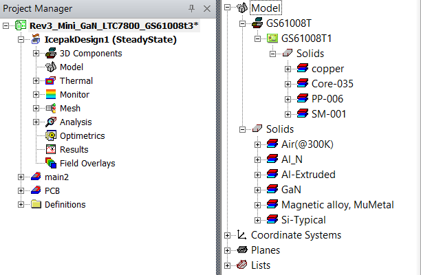
I exported the 3D diagrams from the Altium EDB exporter, so I should have the rights to those components. I have assigned them various materials as shown in one of ANSYS step-by-step simulation tutorials. I imported my EDB file through the ANSYS 3D HFSS and checked to make sure all the stackups/materials matched my Altium project before importing them into the IcePak project. I have attached my different materials for my project. The secondary solids starting with Air(@300K) are all of the component materials I am using, and the solids under the GS61008T are the PCB stackup materials.
 Do you see any issues with the current materials being used?
September 29, 2021 at 12:28 pmPraneeth
Ansys Employee
Please share the thermal analysis image that you have mentioned using the upload image option.
May I know how you have assigned the heat source for your design as it is not clear from your posts?
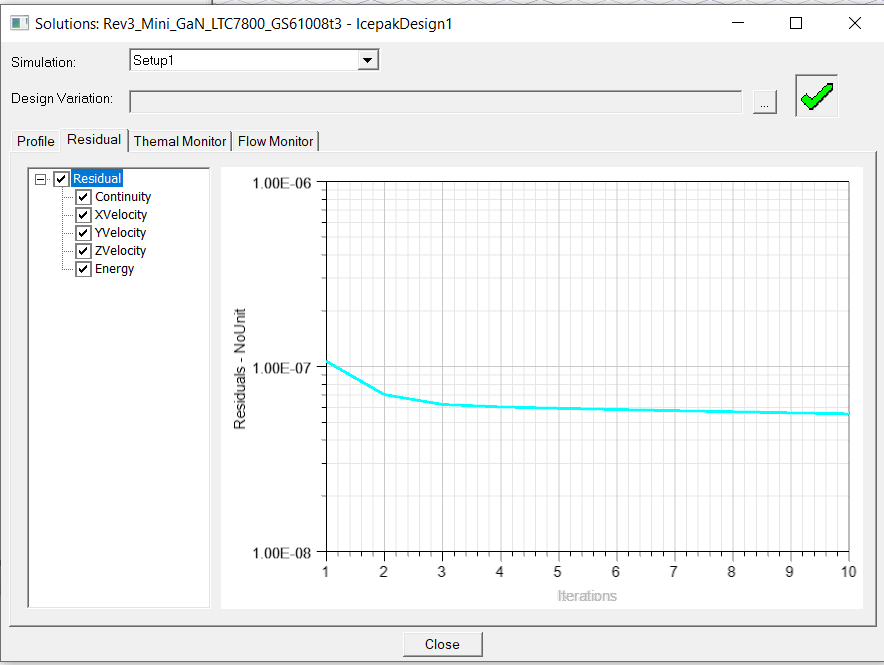
Also share the residual plot after the completion of the simulation.
Best regards.
September 29, 2021 at 4:48 pmnlm54
Subscriber
Please see the attached waveforms. The one is 780mW and the other is about 180mW. I have linked them both as sources and had no luck. The residual plot is shown below with 10 iterations. If I were to extrapolate this plot, then it ends up being much hotter at the 2000 Celsius I described before. I have my analysis (at least I think) set up for thermal conduction with only ambient air dissipating heat.

RegardsSeptember 29, 2021 at 4:49 pmnlm54
SubscriberOctober 18, 2021 at 4:36 pmNikhil Tamhankar
Ansys Employee
Can you please share the images from your model as to how you have set the Thermal boundary condition for the heat to leave the system ? It seems from the residual plot that only the energy equation is being solved for a thermal conduction only type analysis. Hence, even though the air region is present in the Icepak model, there is no convection to take the heat from the solids to the air. Air being a bad conductor of heat might cause the temperatures to rise to very high values which might be the results you see now. If you wish to perform a conduction only analysis, then please make sure that that a Wall BC is set on one of the SOLID parts either as a Fixed Temperature or a Heat Transfer Coefficient value. The Air Region then can be either deleted or made Non Model.
October 18, 2021 at 4:37 pmNikhil Tamhankar
Ansys EmployeeHi .
Can you please share the images from your model as to how you have set the Thermal boundary condition for the heat to leave the system ? It seems from the residual plot that only the energy equation is being solved for a thermal conduction only type analysis. Hence, even though the air region is present in the Icepak model, there is no convection to take the heat from the solids to the air. Air being a bad conductor of heat might cause the temperatures to rise to very high values which might be the results you see now. If you wish to perform a conduction only analysis, then please make sure that that a Wall BC is set on one of the SOLID parts either as a Fixed Temperature or a Heat Transfer Coefficient value. The Air Region then can be either deleted or made Non Model.
October 24, 2021 at 12:39 pmKalembria
SubscriberHow come this was avaiable here? Is in the
altium designer price included such features?
Viewing 8 reply threads- The topic ‘Altium-to-EDT Icepak incorrect Thermal Simulation’ is closed to new replies.
Innovation SpaceTrending discussionsTop Contributors-
4678
-
1565
-
1386
-
1242
-
1021
Top Rated Tags© 2025 Copyright ANSYS, Inc. All rights reserved.
Ansys does not support the usage of unauthorized Ansys software. Please visit www.ansys.com to obtain an official distribution.
-
The Ansys Learning Forum is a public forum. You are prohibited from providing (i) information that is confidential to You, your employer, or any third party, (ii) Personal Data or individually identifiable health information, (iii) any information that is U.S. Government Classified, Controlled Unclassified Information, International Traffic in Arms Regulators (ITAR) or Export Administration Regulators (EAR) controlled or otherwise have been determined by the United States Government or by a foreign government to require protection against unauthorized disclosure for reasons of national security, or (iv) topics or information restricted by the People's Republic of China data protection and privacy laws.


