

-
-
September 10, 2021 at 1:45 pm
tpaplham
SubscriberI have recently been running an eddy current model in 3D that generally converges, but to try to reduce both error and runtime, I tried to take advantage of the rotational symmetry of my model and use Maxwell 2D in RZ mode. However, rather than the quick, accurate solutions I was expecting, 2D seems to really struggle with convergence. Even after multiple passes, the error is still changing by several orders of magnitude per pass, and eventually I run into an error where "one side of the equation resulted in infinity or NaN".
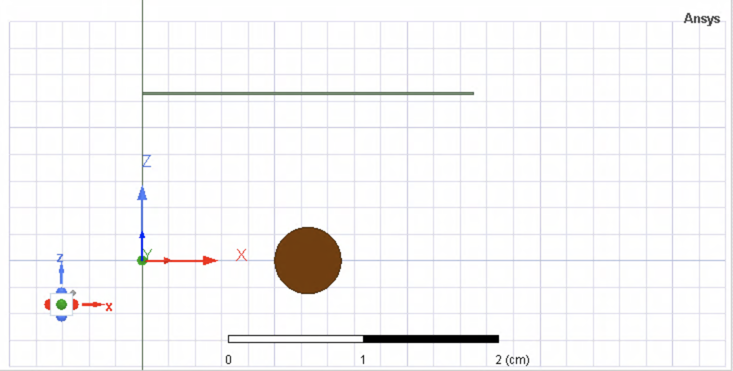
I have attached a screenshot of my geometry. Other than the fact that the top piece is relatively thin (0.152 mm), the geometry is extremely simple, and given that the 3D model, given enough passes/mesh refinement per pass can handle well, I have no clue why the 2D model is having so much trouble. It's definitely the thickness of the sheet that is the source of the issue; removing the sheet entirely, simulating just the axisymmetric coil results in convergence after seconds. I added the sheet back in with a much greater thickness of 0.5 cm, which still resulted in convergence, but even reducing to 0.25 cm (more than an order of magnitude thicker than I need to be able to model) resulted in convergence issues?
Why is the 2D model having such a problem with convergence for this relatively simple model?
September 13, 2021 at 11:10 amNavya Chode
Forum ModeratorHi @tpaplham Change the initial mesh setting to classic and check.
If this didn't solve the issue please share the screenshots of the design and error message.
Ansys employees can't access attachments. Please use the image option and not the Attachment option while sharing the screenshots.
 Regards
Navya
Regards
Navya
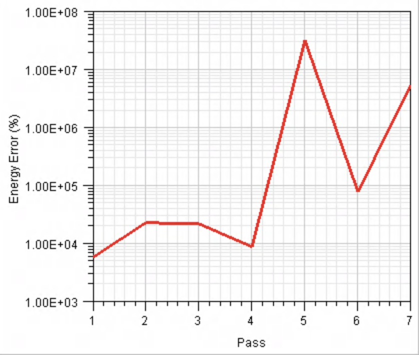
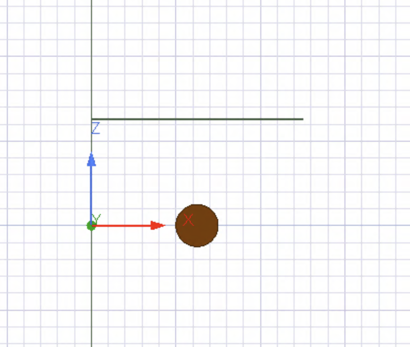
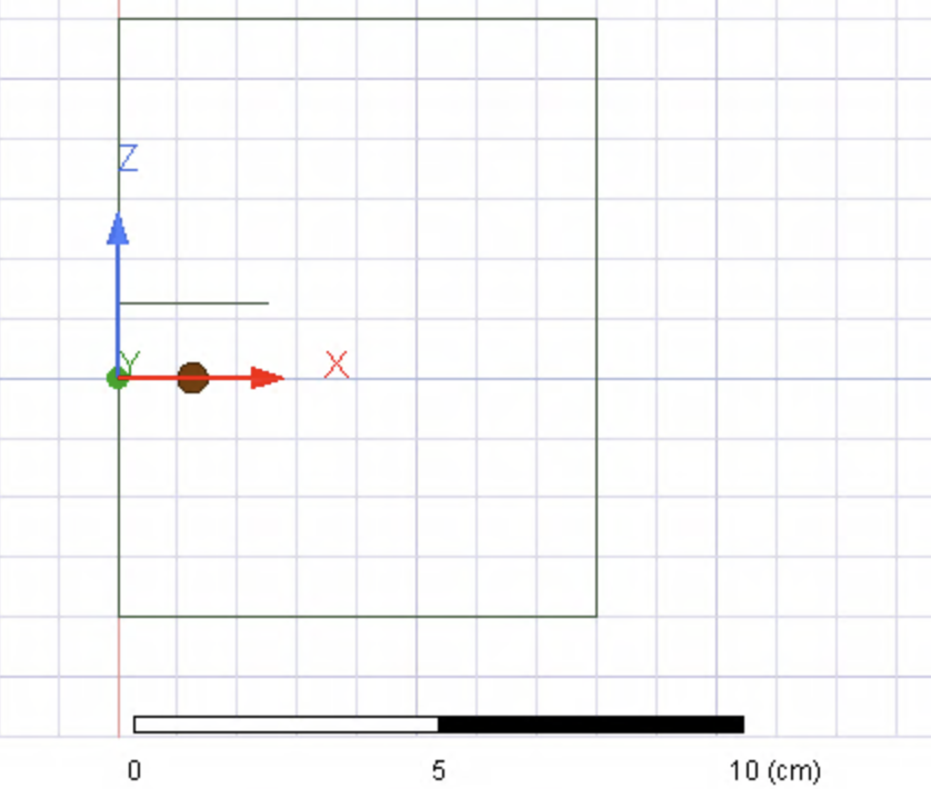
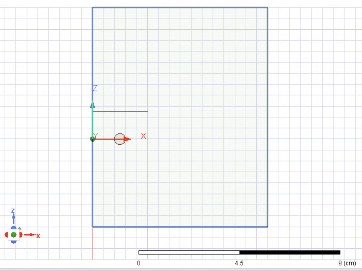
September 13, 2021 at 4:12 pmSubscriberNavya I tried switching the initial mesh setting to Classic but it doesn't appear to have had any noticeable effect. While the latest run has not yet run into the infinity NaN error, it is displaying the same incredibly large energy error and huge jumps to higher and lower errors between passes as before. I have added images of the design and the solution data I am seeing. For reference, I am using the RZ symmetry configuration for the 2D Maxwell simulation, and the boundary condition applied to the region edges (as visible in the more zoomed out image) is the Balloon condition.
-Tyler
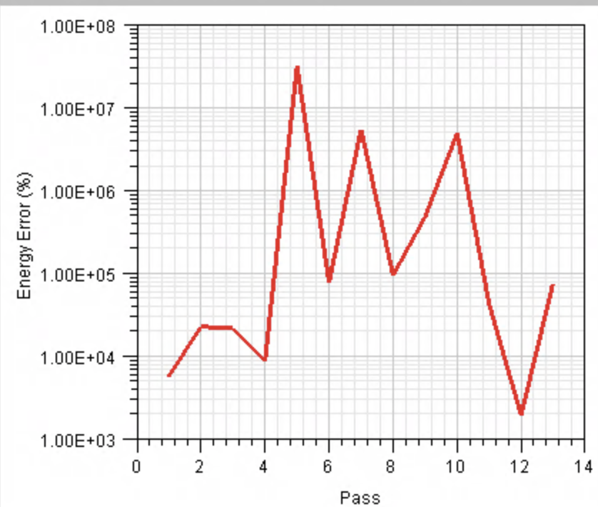
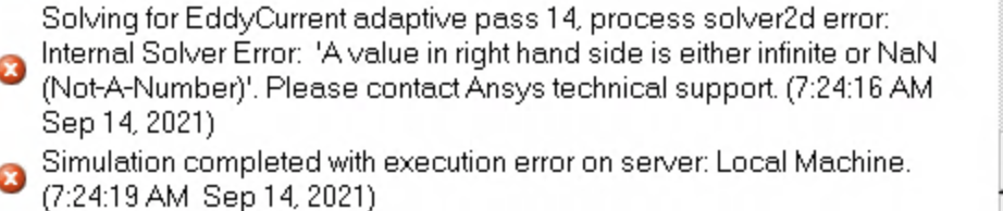
September 14, 2021 at 1:15 pmSubscriberHere is the final energy error report and error message when the simulation terminated after 13/20 passes.
September 16, 2021 at 2:25 amForum ModeratorHi @tpaplham Select and Right mouse click on the thin object(plate)> Assign mesh operation> inside selection> length based and limit the max element length less than the thickness of the sheet.
If this did not work.
Please share a screenshot of excitation, boundary, and other design data, so that I can check.
Regards Navya
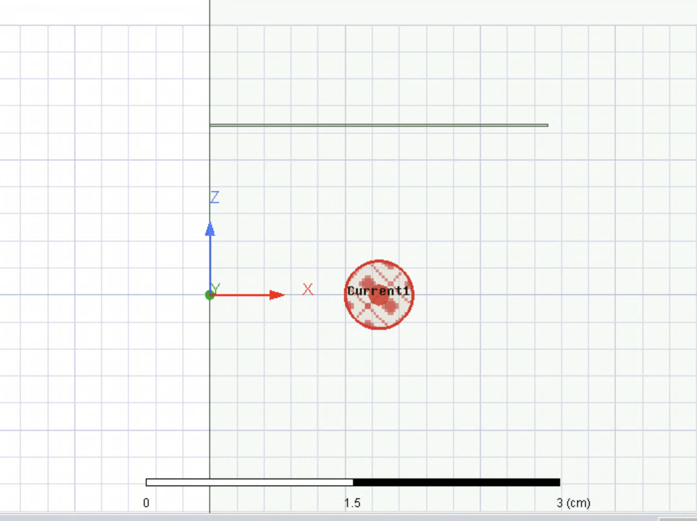
September 17, 2021 at 7:04 pmSubscriberStill doesn't work. The boundary condition is the balloon condition along the polyline highlighted in blue in the first image. The second image shows the Current excitation being applied to the copper wire cross-section.
Viewing 5 reply threads- The topic ‘Maxwell 2D vs 3D simulation’ is closed to new replies.
Innovation Space Trending discussions
 Top Contributors
-
peteroznewman
 6369
6369 -
scabo
 1906
1906 -
Dennis Chen
 1457
1457 -
javat33489
 1308
1308 -
Shyam Prasad V Atri
1022
Top Rated Tags
© 2026 Copyright ANSYS, Inc. All rights reserved.
Ansys does not support the usage of unauthorized Ansys software. Please visit www.ansys.com to obtain an official distribution.
-
Ansys Assistant will be unavailable on the Learning Forum starting January 30. An upgraded version is coming soon. We apologize for any inconvenience and appreciate your patience. Stay tuned for updates.


