-
-
September 5, 2021 at 1:24 pm
Mansoureh
Subscriberhello dear all,
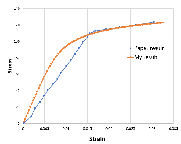
during the simulation of compression test with static structural, I got my result from Deisplaement force and then convert them to stress-strain. There is some differences between the elastic part and I do not know what causes this deviation.
I am verifying my result with an article that they gave me this information about the analysis :
Linear Isotropic Hardening, two rigid bodies up and down of flexible structure moving in quasi-static compression with the strain rate 0.01 mm/s downward (upper plate is moving and the bottom plate is fixed)
They said Ansys non-linear mechanical solver was used to solve the simulation but they did not mention they used explicit dynamic or static structural so I used static structural and i tried to mesh my structure with the element and node very close to their simulation. I have Density, Elastic modulus, and yield stress fo linear Isotropic hardening and I input all the data in the material section
But finally, my result has deviation and how much oi tried to find the reason, I can not understand why there is different between them
Anybody can help me ? or can give me any suggestion?
If i do the analysis with explicit dynamic, may my result change?
If there is needed to put more about the setting please let me know I can put the image to give me more guidance.
I put the any result for the stress-strain figure in comparison with the result from the paper below :
September 5, 2021 at 1:33 pmpeteroznewman
SubscriberI don't believe they used Explicit Dynamics. Can you attach a copy of the paper?
September 5, 2021 at 1:46 pmMansoureh
SubscriberDear peteroznewman
thank you very much for your prompt answer.. thanks a milion.
I put the link of paper here :
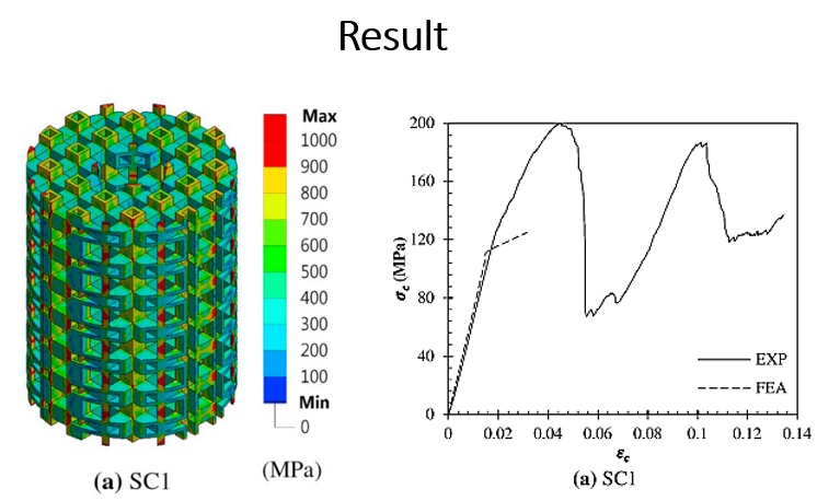
My selected structure from this papare is SC1 ( you can see the result in Fig11 _ a)
September 5, 2021 at 2:28 pmMansoureh
SubscriberDear Could you open the paper? I am worried that you can not open it. Please let me know
September 5, 2021 at 3:26 pmpeteroznewman
SubscriberNo, I don't have access to that paper.
September 5, 2021 at 4:13 pmMansoureh
SubscriberHow can I send it to you? could you please send me your email to share the file with you?
Is it possible to send it to you by linkedin?
September 5, 2021 at 7:03 pmpeteroznewman
SubscriberYou can just insert some screen images of the relevant bits from the paper that show the material model they used into your reply.
September 5, 2021 at 8:27 pmMansoureh
Subscriberthank you very much that you help me to be sure about my result or if I am going wrongly, show me the correct way. Your help is valuable for me .
I put all the explanation about the simulation process below in images and I will ask my question that I am in doubt about them.
the high of the scaffold is 19.6 mm.


 my questions:
what do they mean about the nonlinear mechanical solver? I used static structural with physics performance " mechanical " Is it correct?
What is the difference between " Mechanical" and "nonlinear Mechanical " in physics performance ? I know the mesh setting is a little bit different between them but do they have any effect on the result?
2.I meshed my structure to be close to their number of elements and nodes ( not the same but very close) but I do not know how can I do mesh refinement. I just tried that before to use convergence for von misses stress and put the number for accuracy on 5% but the result did not change( stress changes but very very small). can you guide me about this step? after that, the mesh size did not change and they was the same as before the convergence process and I could not see the min size and max size of the mesh and it seemed all the mesh was the same as the beginning.
3.why do not I have the sharp corner in my stress-strain figure ( my stress-strain curve obtained from Force displacement for the whole body)?
4.In the last image that i attached from the article you can see they did not apply 10% of the height (10%*19.6mm = 0.196 mm) in FEM simulation. for having 0.03 strain we should apply 0.394 mm displacement and 0.196 is related to all the processes in failure up to 0.14 strain. I applied 0.39 in i put END TIME =10, Initial and minimum =100 and max time step 1000. I played with this value but nothing changes and i got the same graph.
5.How did you figure out this is not explicit? could you please explain a little bit?
If you need my settings please let me know to put here to show you maybe I went wrong somewhere.
I got mane errors for previous tries but I solved all of them and convergence goes very well as well. I do not know why there is difference between the elastic part ,
6.I should mention that I did not have tangent modulus ( they did not say anything about that ) and I put it 1.25 GPa from another article. I sent an email to them to give me the value. I hope they answer. Do you think it has effect on the figure ?
7.do you think heat treatment that they did for the manufactured structure has an effect on the result of FEM,do I need to do sth special for that in ANSYS ?
Dearalways I wished you answer my questions. and now when I saw your reply :), It was a dream. Realy, Thanks for your help. your time and your help are really worth it to me.
Sincerely yours
Manoureh
September 5, 2021 at 10:09 pmpeteroznewman
SubscriberStatic Structural is the correct solver. You are using a nonlinear material and large deflection (I hope). Show your analysis settings.
Mesh convergence is typically done by solving once with a coarse element size, then manually using smaller elements, especially near the high stress regions and obtaining another value of the important result, such as Force vs Displacement. This is done several times and the the Force as a function of element size is put on a chart to see if it is changing.
You don't have a sharp corner because you used a Tangent Modulus of 1.25 GPa. The authors used a Tangent Modulus of 0. I know that because they used the words Perfectly Plastic in the text.
I think you have made the correct setting for displacement since the initial slope of the stress-strain curve matches the paper quite well.
They didn't say Explicit and they did say nonlinear mechanical.
That is wrong. See #3 above.
No.
Good luck!
September 6, 2021 at 10:06 amMansoureh
SubscriberDear Thank you very much for spending your time. the words can not describe your favor. I hope I can get my result and my mind will be in peace.
1.yes, I used nonlinear material (Bilinear Isotropic hardening) and defined all the required data. I set large deflection ON
2..I did not do mesh convergence very carefully but how we can change the mesh near the high-stress region? In this type of structure (like scaffolds) there are a lot of sharp corners or holes or maybe thin walls, I think it would be very time-consuming to do that manually and I also do not know how to do that. I can search or if there is any link to share with me, it would be great for me to learn.
3.actually, I tested it before with a tangent modulus of 0 but unfortunately, the result was the same, and nothing happened just the region after yield was dropped down and I still had this curve without any sharp corner . then I switch on using 1.25 GPa but I so nothing happened. just the region after yield was fitted on the paper result but the elastic region still has problem, It seems some point in this area have been lost and ANSYS can not simulate their behavior ( I guess it)
4.Peter, but the slope of my solution does not match with the paper. this slope is the modulus of elasticity of scaffold and it is so important thing that should be considered always and there is a huge difference between my result and this paper. they computed it around 8 GPa and for me, it is around 13 GPa! (a huge difference, with a huge error. The error should be around 2 or 3 )
analysis setting
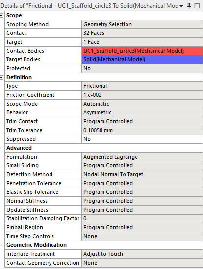
 Connection setting for both plate and scaffold ( I used frictional instead of frictionless contact because my scaffold was sacaped during the simulation, I know the frictional contact has effect on the result but how could constraint my scaffold to prevent moving in frictional contact? )

I used this connection setting according to help and documentation of ansys for rigid body-flexible contact. I hope they are correct.
Dear Peter, thanks again.
September 6, 2021 at 5:54 pmpeteroznewman
SubscriberDear Good.
You set the Element Size as a Parameter and select a Result as a Parameter then let the Parameter Study automatically run through a set of element sizes. It might be the number of elements through the thickness: 1, 2, 3, 4 linear elements and then repeat for quadratic elements. The problem is you will need a big computer with lots of RAM and storage to run this, or do it on a 1/8 symmetry model to reduce your model size.
Have to look into that more closely. Investigations should be done on a 1/8 symmetry model to get results more quickly.
Yes, I was wrong when I said it matched. It clearly does not. I believe you used linear tetrahedral elements and have only 2 elements through the thickness, so that is overly stiff compared with using quadratic elements and more elements through the thickness. I think the Mesh convergence study on the 1/8 symmetry model may show how the slope of the linear elastic portion of the graph changes with element order and number of elements through the thickness.
Viewing 10 reply threads- The topic ‘My result does not match for verification of compression test, any body can help me to understand?’ is closed to new replies.
Innovation SpaceTrending discussionsTop Contributors-
4663
-
1545
-
1386
-
1230
-
1021
Top Rated Tags© 2025 Copyright ANSYS, Inc. All rights reserved.
Ansys does not support the usage of unauthorized Ansys software. Please visit www.ansys.com to obtain an official distribution.
-


Ansys Assistant

Welcome to Ansys Assistant!
An AI-based virtual assistant for active Ansys Academic Customers. Please login using your university issued email address.
Hey there, you are quite inquisitive! You have hit your hourly question limit. Please retry after '10' minutes. For questions, please reach out to ansyslearn@ansys.com.
RETRY


