TAGGED: solver-ansys-mechanical, symmetry-region
-
-
September 2, 2021 at 7:37 pm
WolfgangNeil
SubscriberI'm trying to replicate a quarter symmetric model of a thin tube structure. The symmetry conditions have been assigned across symmetric surfaces using the ANSYS inbuilt "Symmetry" options using proper surfaces and symmetry normals. However, the results differ from the full-scale model. Any suggestions to resolve the mismatch in the results?
September 3, 2021 at 12:58 ampeteroznewman
SubscriberPlease post images of the quarter symmetric model. Show the loads and boundary conditions and the results. Also post the full model details and results so we can see the mismatch you are describing.
September 3, 2021 at 8:05 pmSeptember 5, 2021 at 6:05 amWolfgangNeil
SubscriberSeptember 5, 2021 at 10:28 pmpeteroznewman
SubscriberThanks for the picture.
The Bottom is showing a Fixed Boundary Condition.
The boundary condition: Ux = Uz = 0 and URx = URy = 0 is not a Symmetry Boundary Condition.
A Symmetry Boundary Condition has Uz = 0 and URx = URy = 0 for a face whose normal is parallel to the z axis.
If you create a Symmetry Region in Workbench, you have to be careful because it defaults to the normal parallel to the x axis, regardless of the face that you picked.
September 6, 2021 at 11:00 amWolfgangNeil
Subscriber@peteroznewman
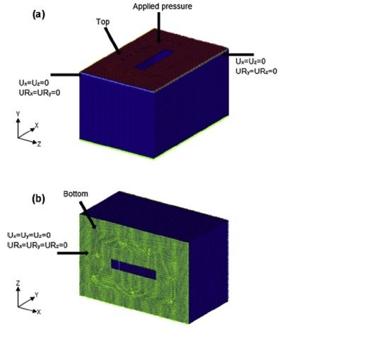
Actually, Ux = Uz = 0 and URx = URy = 0 are applicable to both long edges on the top of the body. Please tell me know if I'm missing something.
Also, it would be very helpful if you can please share some relevant material to understand more about symmetry boundary conditions.
I've prepared a 1/4 model of the body and (referring to the coordinate system of the image) assigned end faces with z-axis as area normal of the model with Symmetry and normal as z-axis. Similarly, I've assigned end faces with x-axis as area normal of the model with Symmetry and normal as x-axis.
I'm using ANSYS 18.1 and the software provides an option to change the symmetry normal as per the geometry selection.
September 7, 2021 at 10:19 pmpeteroznewman
SubscriberYou say Ux = Uz = 0 and URx = URy = 0 are applicable to both long edges on the top of the body, but that is not symmetry. That is symmetry on the plane normal to z and an additional Ux = 0. Where does that come from?
September 8, 2021 at 9:55 amWolfgangNeil
Subscriber@peteroznewman
Sorry, I didn't get your question.
Can I conclude that I will have to analyze this geometry as a full model?
September 8, 2021 at 9:06 pmpeteroznewman
SubscriberI'm saying that you can either use two Symmetry BCs on two orthogonal planes or you can apply the constraints shown in the image, but if you do that, don't call it symmetry.
Symmetry means the normal displacement to the plane and two rotations in the plane are set to 0.
The constraints shown in the image have symmetry and an extra displacement set to 0 which prevents nodes from moving in the plane of symmetry in one direction only! How is that achieved in reality? This constraint pattern is no longer what anyone would call a symmetry BC.
September 9, 2021 at 7:00 amWolfgangNeil
Subscriber@peteroznewman
Now I can understand the point you are trying to make.
Thank you for your kind cooperation in understanding the matter.
Viewing 9 reply threads- The topic ‘Symmetry model’ is closed to new replies.
Ansys Innovation SpaceTrending discussionsTop Contributors-
3492
-
1057
-
1051
-
965
-
942
Top Rated Tags© 2025 Copyright ANSYS, Inc. All rights reserved.
Ansys does not support the usage of unauthorized Ansys software. Please visit www.ansys.com to obtain an official distribution.
-