

TAGGED: Lumerical-FDTD
-
-
August 30, 2021 at 5:34 pm
amora
SubscriberHello,
I have a design of a periodic array of cylinders. I am using:
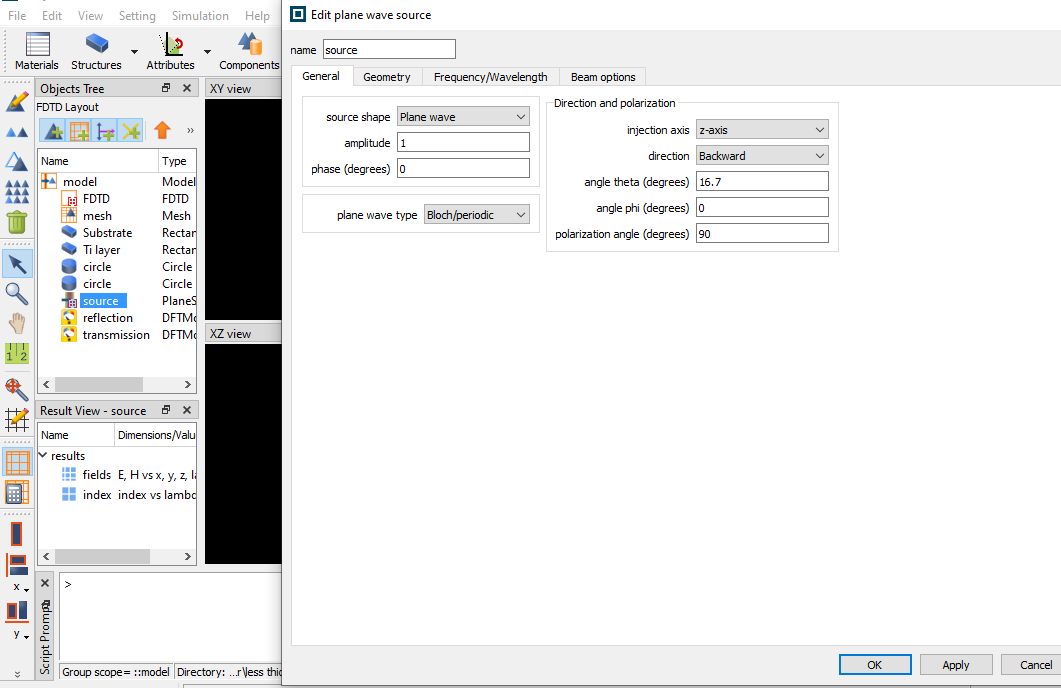
1- inclined injection not perpendicular injection (angle theta =16.7 instead of 0)
2- 90 polarized incident wave instead of 0 polarized wave, please check photo 1 to see my settings
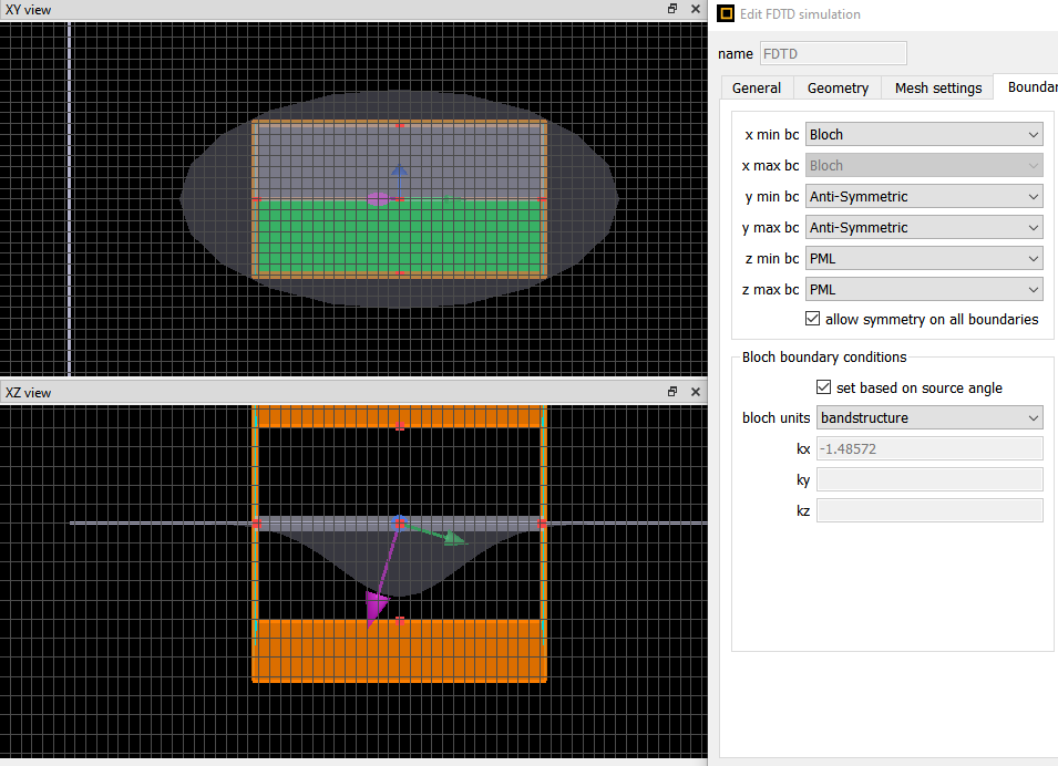
I have a question regarding the boundary conditions I should use. I believe that I should use symmetric for x-min & x-max and anti-symmetric for y-min & y-max, is it right please? Or should I use periodic boundary condition for both x and y directions? Please let me know the correct one and why, thanks. Also, do I need to change any other settings away from the boundary condition to consider the inclined injection and 90 polarized wave?
August 31, 2021 at 7:36 pmTaylor Robertson
Ansys EmployeeThe nonzero theta will break the symmetry in the direction of the tilt. In that direction X you will need to use Bloch BC. With the polarization settings the E field will be rotated so anti-symmetry in Y direction is the correct choice.
You may need to play with the PML settings if you experience reflection or instability. Usually I would start with the default settings.
-Best
September 1, 2021 at 5:13 pmSubscriber
Thank you for your reply.
What about simulation time please? I did the simulation using the boundary conditions you mentioned and increased the simulation time from 10000e-15 to 23000e-15 and the simulation didn't reach the auto shutoff condition, does it mean that the results are inaccurate? Usually without symmetric BC, it's very hard to reach the auto shutoff condition without greatly increasing the simulation time.
Also, if I changed the polarization to 0 with same injection angle (angle theta =16.7 instead of 0), the new boundary conditions will be Bloch BC for x and symmetric for y, is it correct? Thanks.
September 3, 2021 at 9:45 pmSubscribercan you please my question? I still need answer
September 6, 2021 at 3:22 pmGreg Baethge
Ansys Employee
Today is a public holiday in Canada so I take the liberty to get back to you on this topic. Regarding the simulation time, FDTD is a time domain technique and we rely on a Fourier transform to get the frequency domain fields. For that reason, we need the fields to be weak by the end of the simulation to avoid numerical artifacts in this Fourier transform.
FDTD will monitor the fraction of energy left in the simulation volume (this is the auto shutoff value). If it doesn't reach the threshold (1e-5 by default), there is a chance the Fourier transform will show these artifacts. Note multiple factors can affect the auto shutoff:
Simulation time
Reflection from PML
Stability issue
etc.
As my colleague mentioned, you may need to play with the PML settings, for example use the "steep angle" profile, increase the number of layers.
If your simulation is broadband, keep in mind the source angle depends on the wavelength (see this).
Also, if the simulation shows some stability issue (for example, either the auto shutoff value increases or never really gets smaller), you may want to check this page about diverging simulations.
Regarding the boundary conditions, you're correct, you can set x to Bloch, and y min and y max to symmetric.
September 8, 2021 at 1:59 pmSubscriberThanks for your reply
Viewing 5 reply threads- The topic ‘Boundary conditions for inclined incidence’ is closed to new replies.
Innovation Space Trending discussions
 Top Contributors
-
peteroznewman
 6455
6455 -
scabo
 1906
1906 -
Dennis Chen
 1457
1457 -
javat33489
 1308
1308 -
Shyam Prasad V Atri
1022
Top Rated Tags
© 2026 Copyright ANSYS, Inc. All rights reserved.
Ansys does not support the usage of unauthorized Ansys software. Please visit www.ansys.com to obtain an official distribution.
-


