
TAGGED: beam-analysis, constraint, rigid-body-motion, shell, shell-elements
-
-
August 18, 2021 at 8:34 am
BenediktaSchmidt
SubscriberHi,
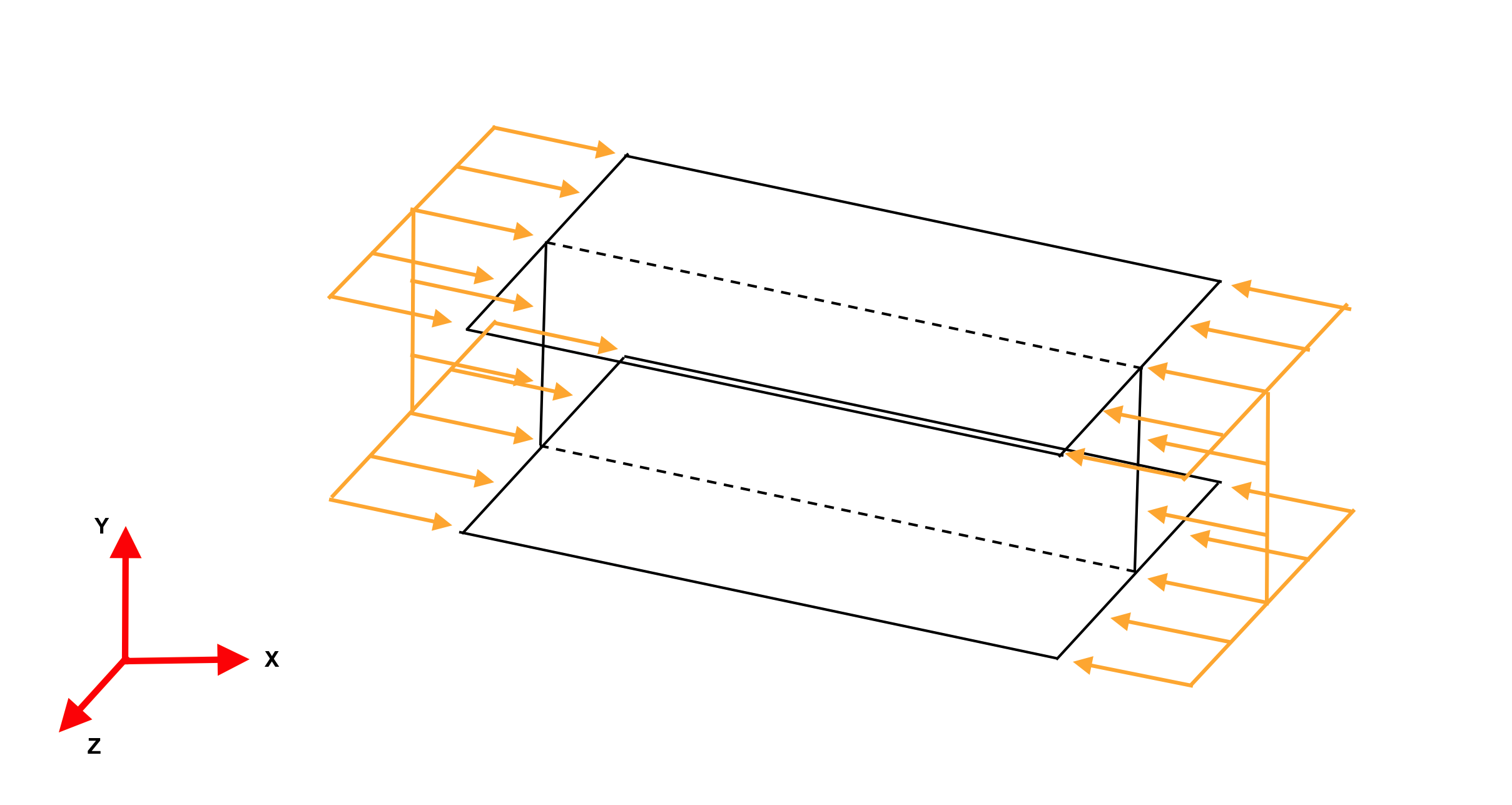
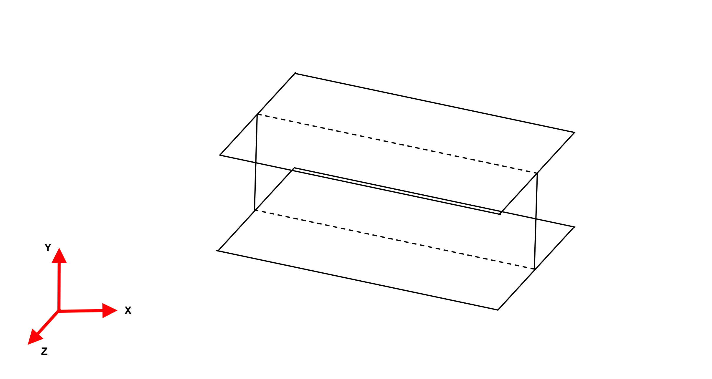
I want to study a compressed beam in Ansys Mechanical APDL. To model the beam I used shell elements.
But, in order to run the analysis, I need to prevent rigid body motions of the beam. How can I do it? Which constraints should I use?
August 18, 2021 at 12:03 pmpeteroznewman
SubscriberWhat do you mean by a "compressed beam"?
When a beam experiences a bending moment, one side goes into tension and the opposite side goes into compression. Is that what you mean?
There are multiple ways to apply a bending moment to a beam. You can do a cantilever beam with an end load, you can do three or four point bending, you can apply a pure moment. You have to say how you want to load your beam first, since the supports that prevent rigid body motion will change depending on the load you want to apply.
August 18, 2021 at 2:13 pmSubscriberI want to simulate a beam compressed by both sides (on the web and on the flanges). The problem itself doesn't need any constraint, because it is auto-equilibrated, but to run analysis on Ansys I need to prevent the rigid body motion (translations ad rotations). I hope I was clear enough :) .
August 21, 2021 at 8:49 pmSubscriberSelect all the edges on the -X and use a Remote Displacement, Behavior = Deformable, then set all six DOF to 0.0 to hold one end fixed without adding any stiffness and have no forces at the -X end. Only apply forces at the +X end.
Another approach is to have no constraints and turn on Inertia Relief, then you can have equal and opposite forces.
A final approach is to have equal and opposite forces but pick just three vertices on the flange. The bottom vertex at the left end can have 0,0,0 for X,Y,Z. The bottom vertex at the right end can have Y and Z set to zero displacement then finally pick a top node at the left end and set Z = 0.
August 23, 2021 at 8:43 amSubscriberI already tried by picking just three vertices on the flange. By doing this I notice that the reaction forces at the fixed boundary conditions (i.e. the supports) are very close to zero, and I think that means that the choice of the boundary conditions was correct. Although this I'm not sure if by proceeding with this method it's possible to run a non-linear analysis (or an eigenvalue analysis), because I keep receiving the warning that the solution does not converge and I've read on the internet that a limitation of the 3-2-1 method is that it is not applicable to non-linear geometry cases. Is that true?
August 23, 2021 at 12:04 pmSubscriberThe 3-2-1 method can be used in a large displacement nonlinear solution for a shell element model. The problem for solid elements would be the stress singularity that is created by selecting three points. But in a case with reaction forces that are very close to zero, that would not be a problem.
An eigenvalue analysis will run with a 3-2-1 method of constraint.
There are many reasons a nonlinear solution fails to converge. You have to look at why it failed to converge. What is the specific error message near the end of the Solution Output text listing?
Viewing 5 reply threads- The topic ‘How to prevent rigid body motion on a 3D-Beam Model’ is closed to new replies.
Innovation Space Trending discussions
 Top Contributors
-
peteroznewman
 6450
6450 -
scabo
 1906
1906 -
Dennis Chen
 1457
1457 -
javat33489
 1308
1308 -
Shyam Prasad V Atri
1022
Top Rated Tags
© 2026 Copyright ANSYS, Inc. All rights reserved.
Ansys does not support the usage of unauthorized Ansys software. Please visit www.ansys.com to obtain an official distribution.
-


The Ansys Learning Forum is a public forum. You are prohibited from providing (i) information that is confidential to You, your employer, or any third party, (ii) Personal Data or individually identifiable health information, (iii) any information that is U.S. Government Classified, Controlled Unclassified Information, International Traffic in Arms Regulators (ITAR) or Export Administration Regulators (EAR) controlled or otherwise have been determined by the United States Government or by a foreign government to require protection against unauthorized disclosure for reasons of national security, or (iv) topics or information restricted by the People's Republic of China data protection and privacy laws.
