

-
-
August 6, 2021 at 12:14 pm
2011303
Subscriber我采用了文献《Numerical simulation of nonlinear second harmonic wave generation by the finite difference frequency domain method》的例子,设置基波在真空中的波长为1064nm,然后先新建了一个材料模型LN,其在1064nm处折射率为2.156,在532nm处折射率为2.2342,再新建一个chi2模型,选择LN为基材,设置二阶极化率为27.2pm/V.为减少反射损耗,将背景材料设置为LN。其他设置仿照官网给出的非线性例子进行了设置。
我将监视器得到的波印廷矢量进行积分得到倍频功率后再将倍频功率比上光源功率得到非线性转换效率。对晶体长度进行扫描后发现得到的非线性转换效率随晶体长度的图与文献中给出的图对应不上。请问我在仿真文件中的设置出了哪些问题。
August 6, 2021 at 9:50 pmGuilin Sun
Ansys Employee以后写中文的话请将问题发在中文论坛 Photonics - Chinese — Ansys Learning Forum 与文献结果不一致的原因很多,参见 Ansys Insight: 我的仿真结果为什么与文献或实验结果不一致? 其中这句话,“为减少反射损耗,将背景材料设置为LN”是否与文献一致?实验是不可能在这个材料内部测量功率的,你要看看文献是在哪里如何量测倍频功率的。同时,现在的网格精度是针对基频的,你可能性需要至少精度4或者5才能保证倍频的精度在Mesh Accuracy 2。 请斟酌一下。August 9, 2021 at 3:24 amSubscriber首先非常抱歉将问题发错了地方,我以后会注意的。 然后我仔细地学习了官方的“非线性仿真”视频,解决了上述问题。为了交流学习,我总结一下我犯的错误。 1、那篇文献其实是一篇用其他方法的仿真文献,“为减少反射损耗,将背景材料设置为LN”是我的理解,但实际上不需要设置背景材料,直接将光源和监视器放在非线性介质里面就可以了。 2、实际上也不需要扫描,在多个位置上设置监视器就能够监控不同位置上的非线性转换效率,之前正是因为扫描所以我才设置较小的网格精度。 3、下面附件附上了我的仿真文件,想要学习的朋友可以看一下。This is an embed external element. It can be deleted using the delete key or the backspace key. To view the full element, press the preview button below.SHG.7z4.51 MBAugust 9, 2021 at 3:23 pmAnsys Employee谢谢总结,祝你学研不断进步!
April 14, 2022 at 4:02 pmzhaoyaotian
Subscriber请问一下这里的非线性频率的"能量"(或者相对能量),为什么是用透射率乘source power来计算的:
power_w0=T_w0*sourcepower(f);
但是官网给出的另一个例子用的是坡印亭矢量的积分来算的:
#!3D simulation:
# disable CW norm
nonorm;
# get poynting vector from monitor.
Poynting = getresult("monitor","P");
# integrate real Pz to get power. Assume this monitor is 2D, in the YZ plane
# This quantity will have units of Watts/Hz^2 due to the use of the nonorm state
Trans = 0.5 * integrate(real(pinch(Poynting.Px)),1:2,pinch(Poynting.y),pinch(Poynting.z));
# package data into dataset
T = matrixdataset("T"); # initialize dataset
T.addparameter("lambda",c/Poynting.f,"f",Poynting.f); # add frequency parameter
T.addattribute("T",Trans); # add transmission attribute
# optionally, visualize data
visualize(T);
而我在采用后一种算法进行计算时,并不能得到一个w0的光和2w0的光之间,相互耦合的结果(由于相位失配)。
想请教一下这是为什么。
April 16, 2022 at 9:20 pmAnsys Employee"请问一下这里的非线性频率的"能量"(或者相对能量),为什么是用透射率乘source power来计算的:"
是为了得到“绝对”的数值。
“而我在采用后一种算法进行计算时,并不能得到一个w0的光和2w0的光之间,相互耦合的结果(由于相位失配)。”
我不清楚你说的相互耦合是什么意思,当你的监视器有记录这两个波长的结果时,就应该能得到这两个波长的积分。你没有得到这两个波长的积分结果说明监视器没有记录。
May 18, 2022 at 3:36 amWenheJia
Subscriber老师您好,想向您请教一个问题。您提到说“将监视器得到的波印廷矢量进行积分得到倍频功率后再将倍频功率比上光源功率得到非线性转换效率”,但是我在仿真中遇到这样一个问题。我在仿真相同材料两种结构参数的四波混频过程中,得到的坡印廷矢量光谱结果如图所示。其中图一中谐波的峰值功率更高,坡印廷矢量积分值也更高,但是信噪比更低(噪声基线值更高),这样该如何比较两种结构的效率呢?谢谢老师。
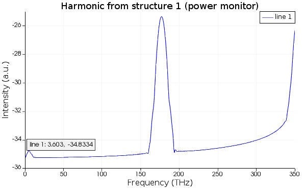
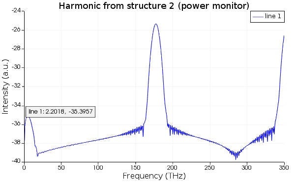
May 18, 2022 at 3:36 amSubscriber
May 18, 2022 at 2:56 pmAnsys Employee转换效率与信噪比无关吧,这个应该是一个理论问题,具体琢磨处理由你们决定,仿真只是给出基本结果。
Viewing 8 reply threads- The topic ‘非线性晶体的二次谐波产生仿真结果与文献结果对不上’ is closed to new replies.
Ansys Innovation Space Trending discussions
 Top Contributors
-
peteroznewman
 3967
3967 -
scabo
 1431
1431 -
Dennis Chen
 1272
1272 -
javat33489
 1119
1119 -
Shyam Prasad V Atri
1015
Top Rated Tags
© 2025 Copyright ANSYS, Inc. All rights reserved.
Ansys does not support the usage of unauthorized Ansys software. Please visit www.ansys.com to obtain an official distribution.
-


The Ansys Learning Forum is a public forum. You are prohibited from providing (i) information that is confidential to You, your employer, or any third party, (ii) Personal Data or individually identifiable health information, (iii) any information that is U.S. Government Classified, Controlled Unclassified Information, International Traffic in Arms Regulators (ITAR) or Export Administration Regulators (EAR) controlled or otherwise have been determined by the United States Government or by a foreign government to require protection against unauthorized disclosure for reasons of national security, or (iv) topics or information restricted by the People's Republic of China data protection and privacy laws.


