

TAGGED: boundary-conditions, capacitor, lumped-impedance, maxwell
-
-
August 4, 2021 at 9:42 pm
Louis0201
SubscriberDear all
hope you guys are being well.
I am louis.
New to Maxwell, HFSS.
Currently, I am trying to create a circuit model in ANSYS Maxwell 3D.
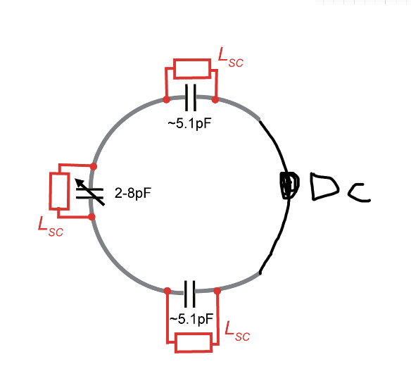
for the following circuits, it is easy for me to create a 3D coil and set the excitation current. However, when it comes to the capacitor and inductor, I found that Maxwell 3D doesn't have Lumped RLC port boundary can set up.
Does anyone know how to set up the impedance boundary condition in ANSYS Maxwell 3D?
thanks in advance!
August 11, 2021 at 1:21 pmNavya Chode
Forum ModeratorHi@Louis0201 If you are trying to do it at the circuit level you can do this in the circuit design.
If you have the actual models, how they are implemented in the real world with all the material information you can import these components into HFSS and conduct the simulation.
In Maxwell the electric and magnetic solvers are separate and hence the capacitor and inductor combination you have shown above can not be achieved in maxwell.
Regards Navya
Viewing 1 reply thread- The topic ‘how to set up the lumped RLC port boundary in Maxwell 3D ?’ is closed to new replies.
Innovation Space Trending discussions
 Top Contributors
-
peteroznewman
 6379
6379 -
scabo
 1906
1906 -
Dennis Chen
 1457
1457 -
javat33489
 1308
1308 -
Shyam Prasad V Atri
1022
Top Rated Tags
© 2026 Copyright ANSYS, Inc. All rights reserved.
Ansys does not support the usage of unauthorized Ansys software. Please visit www.ansys.com to obtain an official distribution.
-


The Ansys Learning Forum is a public forum. You are prohibited from providing (i) information that is confidential to You, your employer, or any third party, (ii) Personal Data or individually identifiable health information, (iii) any information that is U.S. Government Classified, Controlled Unclassified Information, International Traffic in Arms Regulators (ITAR) or Export Administration Regulators (EAR) controlled or otherwise have been determined by the United States Government or by a foreign government to require protection against unauthorized disclosure for reasons of national security, or (iv) topics or information restricted by the People's Republic of China data protection and privacy laws.
