-
-
August 3, 2021 at 11:42 am
Desta
SubscriberCurrently I am working on hydrodynamic design of unconventional hydro turbine. The turbine intended to be installed in canal as such the resistance from the turbine create water level difference in the upstream and downstream of the turbine. One of the main task in the design work is to determine the upstream and downstream water level in the canals, the difference between the water level in the canals is assumed to provide gross head for the turbine. The water levels in the upstream and downstream canals have been determined using energy conservation along a streamline (Bernoulli equation) as first estimation and used to set up the single phase simulation. With single phase simulation I have got seemingly very good result for turbine eff, hydraulic power, mechanical power, net head, gross head etc
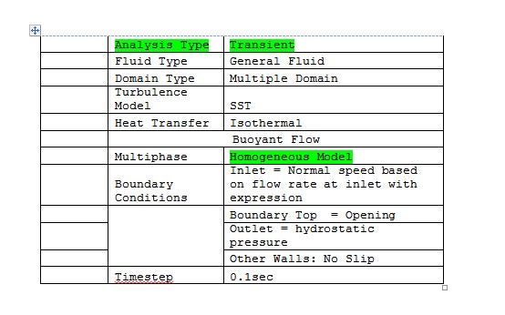
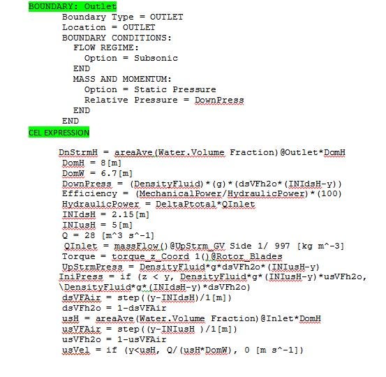
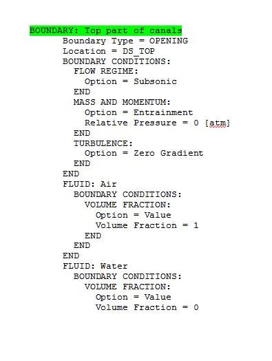
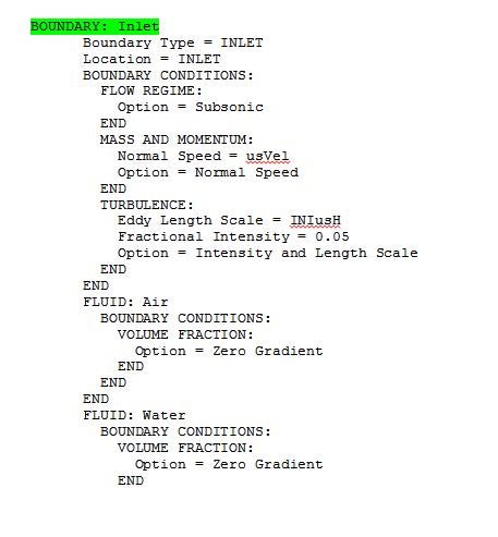
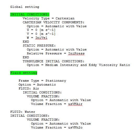
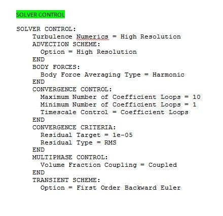
Now further I want to check the water level in the upstream and downstream level as well as other parameters determined from single phase simulation using two phase simulation in ANSYS CFX (Free surface flow). More or less I have applied the techniques suggested by ANSYS CFX tutorial in free surface flow over a bump in chapter 9. The simulation runs quite OK for about 65.5 revolution of the turbine, first i have used larger time step and then decreasing to lower value, to be specific (0.25 sec to 0.1sec). At about the aforementioned revolution of the turbine mass flow is conserved when checked at control surfaces, i.e at inlet and outlet are equal, expected tor is also produced from the turbine.
Problem encountered:
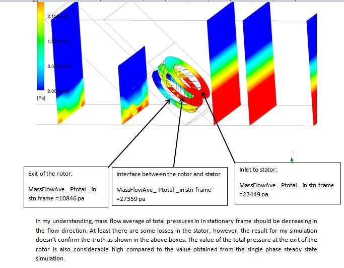
- Total pressure in stationary frame are not conserved in the flow direction. i.e, I am expecting the pressure to decrease from inlet to outlet continuously but this doesn't happened. For instance the pressure at a location where the guidevane interfaced with the rotor is higher than the one at guidevane inlet. Note that the guidevane inlet is upstream of the interface.
- The total pressure in stationary frame at the turbine outlet is much higher than the one obtained from single phase.
- The calculated hydraulic power, which is the product of the change in total pressure in stationary frame between guidevane inlet and rotor outlet, and volume flow rate passing through turbine is much less the mechanical power.
I am waiting for any valuable suggestion why this happened in my simulation. any help is appreciated in advance
August 3, 2021 at 3:41 pmDrAmine
Ansys EmployeeWhat do you want to achieve?
Why multiphase? You used single phase for this as you want to keep free surface level unchanged.
How are accounting for stator-rotor interface? Are you using mixing plane?
Can you post a picture of the problematic and summary of the settings you are using?
Are you student at IHS or Research Assistant?
August 4, 2021 at 3:50 pmDesta
SubscriberThanks Dr Amine for your reply for my post. I will try to clarify the questions you raised as follow:
I think the title I gave to my post might be confusing; to be specific my simulation setup is a free surface flow.
What do you want to achieve? I want to identify clearly the heights at which the water interfaced with air both in upstream and downstream canals. Then, based on the water level change between the upstream and downstream canals, I want to determine the gross power produced by the the turbine. Further, based on total pressure change between guidevane inlet and rotor outlet i want to calculate the hydraulic power and compare it with the torque power. Ultimately compare all these results with single phase simulation results (which is done with free slip wall at top wall of the canals).
How are accounting for stator-rotor interface? I have used transient rotor stator interface with pitch ratio of one.
Can you post a picture of the problematic and summary of the settings you are using?
Are you student at IHS or Research Assistant? I am PhD student but not employed by the IHS. IHS hosted me for a few months to use their facilities.
August 5, 2021 at 8:38 amDrAmine
Ansys EmployeePlease add you screenshots and description in the text and not as attachments.
August 6, 2021 at 8:42 amAugust 6, 2021 at 8:59 amAugust 6, 2021 at 9:03 amAugust 6, 2021 at 9:05 amAugust 17, 2021 at 12:32 pmDesta
Subscriber
Is there any news regarding for the free surface flow problem thread I started few weeks back?
Viewing 8 reply threads- The topic ‘Having problem with two phase flow (air and water)’ is closed to new replies.
Ansys Innovation SpaceTrending discussionsTop Contributors-
3492
-
1057
-
1051
-
965
-
942
Top Rated Tags© 2025 Copyright ANSYS, Inc. All rights reserved.
Ansys does not support the usage of unauthorized Ansys software. Please visit www.ansys.com to obtain an official distribution.
-

Ansys Assistant

Welcome to Ansys Assistant!
An AI-based virtual assistant for active Ansys Academic Customers. Please login using your university issued email address.

Hey there, you are quite inquisitive! You have hit your hourly question limit. Please retry after '10' minutes. For questions, please reach out to ansyslearn@ansys.com.
RETRY