TAGGED: acp-pre, ansys-acp, ansys-mechanical, composite-analysis
-
-
July 16, 2021 at 9:04 am
dtomas
SubscriberHello everyone!
I'm trying to model a composite wing made with a core of foam and a carbon fiber ply around it. To do so, I followed the guidelines in the documentation as well as the class40 example.
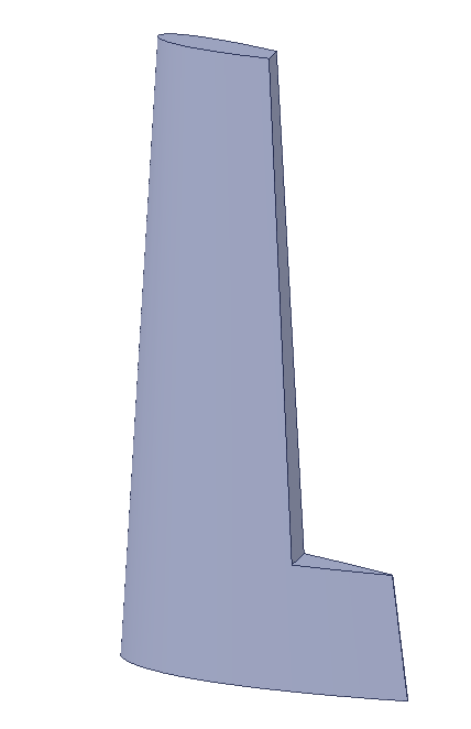
When I provided the CAD geometry of the full wing (pictures bellow)
July 21, 2021 at 7:11 pmSean Harvey
Ansys EmployeeHello @dtomas´╗┐ Here are some ideas to explore.I would still stick with two halves and then they can be bonded contact in Mechanical.
Set the thickness of the core to be larger, then use aGeometry Cut-off Selection Rule at the middle section (mid plane) to trim.If you were to extrude from the OML inward, the mesh may overlap using a solid model, but you can try with shells to see if you can get the core thickness as desired.Also see the cut off geometry in the solid model to cut the extruded elements.
You can also follow procedure 4.4. Analysis of a Mapped Composite Solid Model in the ACP Help where an existing mesh is used. The layup is then mapped and in this case your layup core material.This is a newer technique which works well when we have trouble extruding the shells to create the desired solids models.
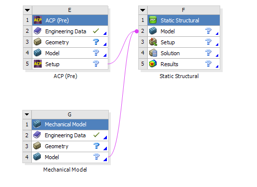
You can also mesh the skin in ACP, mesh the core as a stand alone via the Mechanical Model, then use model assembly as shown below and bonded contact to glue the skin to the core.The disadvantage here is that you won't be able to post-precess the core in ACP, but this is not a big deal since you have likely an isotropic foam, and you can use the scalar failure theories of Von Mises, Max Shear, Max Principal, etc.You don't need the more complex orthotopic failure theories of ACP.This method is the easiest of the 3 to try. Also, you don't need to split the wing top/bottom since you will just model the core as is, not split.
Hope this helps, please provide some feedback. Thank you!
Regards Sean

-
December 6, 2022 at 7:41 am
mine_mew
SubscriberHi Sean,
I am trying to create delamination on a composite blade. This blade is surface geometry and is assembled with many parts but the considered section is the top surface (I want to create the delamination on this part).
I am confused as below;
- To create delamination, the blade geometry should be solid elements.
- The geometry imported to ACP should be the surface type but the ACP can generate to solid element by the "solid model" command. So I don't know how to create delamination after setting parameters in ACP
- I assign the composite stack in ACP (e.g. 0/90/90/0). If I want to create delaminate between 0 and 90. How can I do it?
Could you please suggest me how to create delamination on the composite blade (curve surface)?
Thank you in advance
Panida
Viewing 1 reply thread- The topic ‘Creating Variable Thickness Core in Ansys ACP’ is closed to new replies.
Innovation SpaceTrending discussionsTop Contributors-
5094
-
1830
-
1387
-
1248
-
1021
Top Rated Tags© 2026 Copyright ANSYS, Inc. All rights reserved.
Ansys does not support the usage of unauthorized Ansys software. Please visit www.ansys.com to obtain an official distribution.
-
The Ansys Learning Forum is a public forum. You are prohibited from providing (i) information that is confidential to You, your employer, or any third party, (ii) Personal Data or individually identifiable health information, (iii) any information that is U.S. Government Classified, Controlled Unclassified Information, International Traffic in Arms Regulators (ITAR) or Export Administration Regulators (EAR) controlled or otherwise have been determined by the United States Government or by a foreign government to require protection against unauthorized disclosure for reasons of national security, or (iv) topics or information restricted by the People's Republic of China data protection and privacy laws.


