

-
-
July 12, 2021 at 9:32 am
Parthdesiboy
SubscriberI have been trying to calculate the stress intensity factor in 3D model of SENT specimen. I have first calculated the SIF in 2D model and it was easy to select the pre meshed crack. However, How should i insert crack without removing volume through Boolean or extrusion. I also tried applying crack using split, but it is splitting the whole body though plane.
August 20, 2021 at 2:05 pmdanielshaw
Ansys EmployeeHow should i insert crack without removing volume through Boolean or extrusion. I also tried applying crack using split, but it is splitting the whole body though plane.
A: You can use whatever tools your CAD systems has to create a pre-defined crack. Mechanical also has an arbitrary crack capability that will insert a crack into body without splitting the body.
I am applying pre meshed crack to calculate SIF. Is it enough if i just select a crack tip (edge in 3D) and not also crack faces? What should be the optimum mesh around crack and for model ?
A: You need to define the crack tip and crack coordinate system. You need to define the crack faces, if you want to apply loading inside the crack. There is no precise definition of an acceptable mesh, but a well-shaped, refined mesh is required. Wedge shaped elements at the crack tip are preferred, but not required. Tet elements are not recommended, but are allowed.
I also tried using symmetry in model and select pre meshed crack. However, the SIF seems incorrect as it is same around 80 MPa m^0.5 for all crack length.
A: symmetric boundary conditions are supported. I do not know why the SIFs are not changing. Does changing the mesh affect the results? What is a reasonable SIF estimate based on hand calcs.
October 1, 2021 at 2:29 pmSubscriberThank you Daniel for your answer.
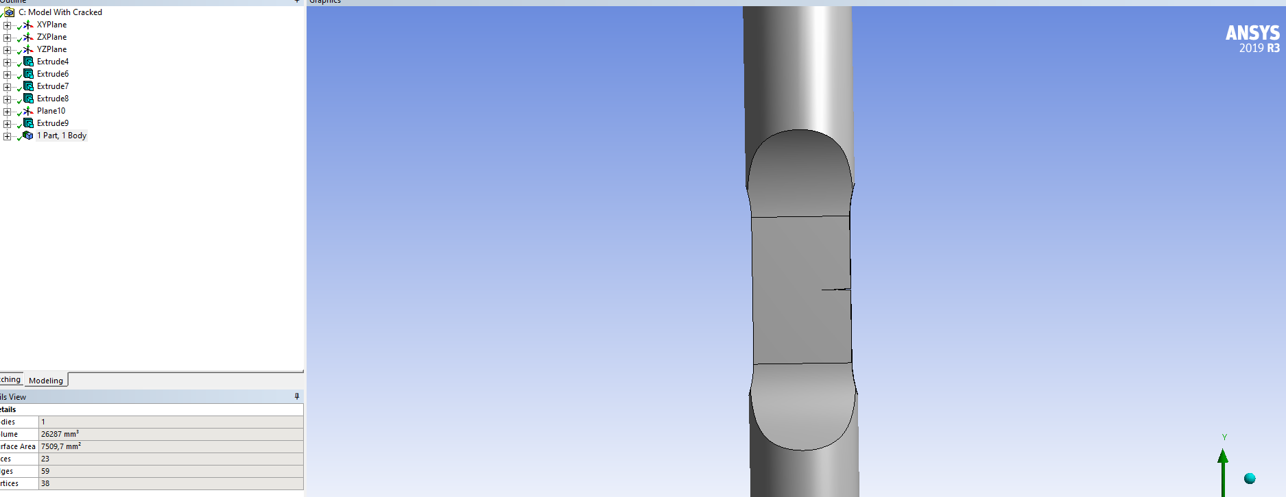
I am using the symmetric boundary and also do not need to apply loading on the crack faces. I have tried meshing the model best possible way. I use the Tetrahedrons method. meshed model is as shown below.
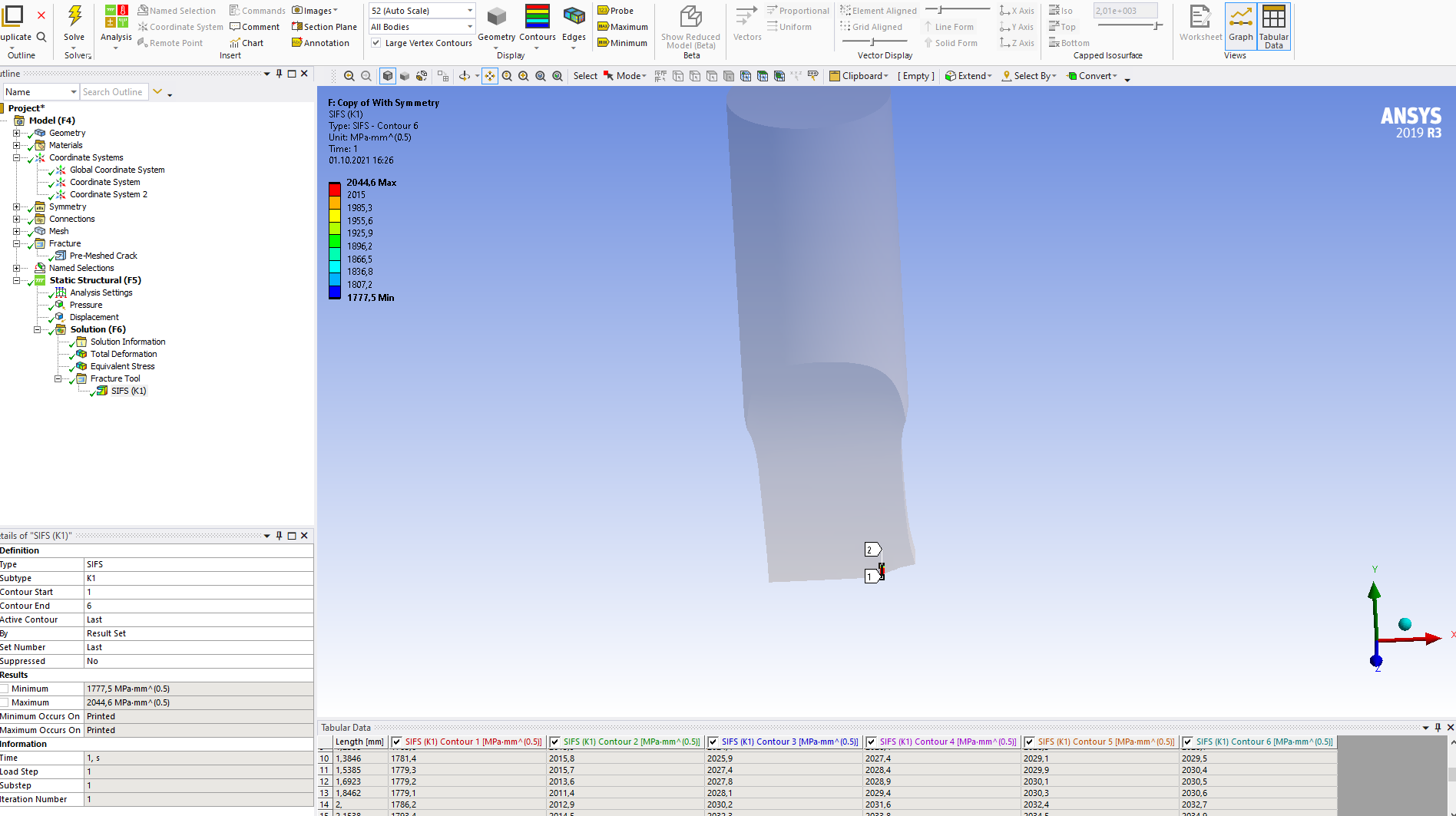
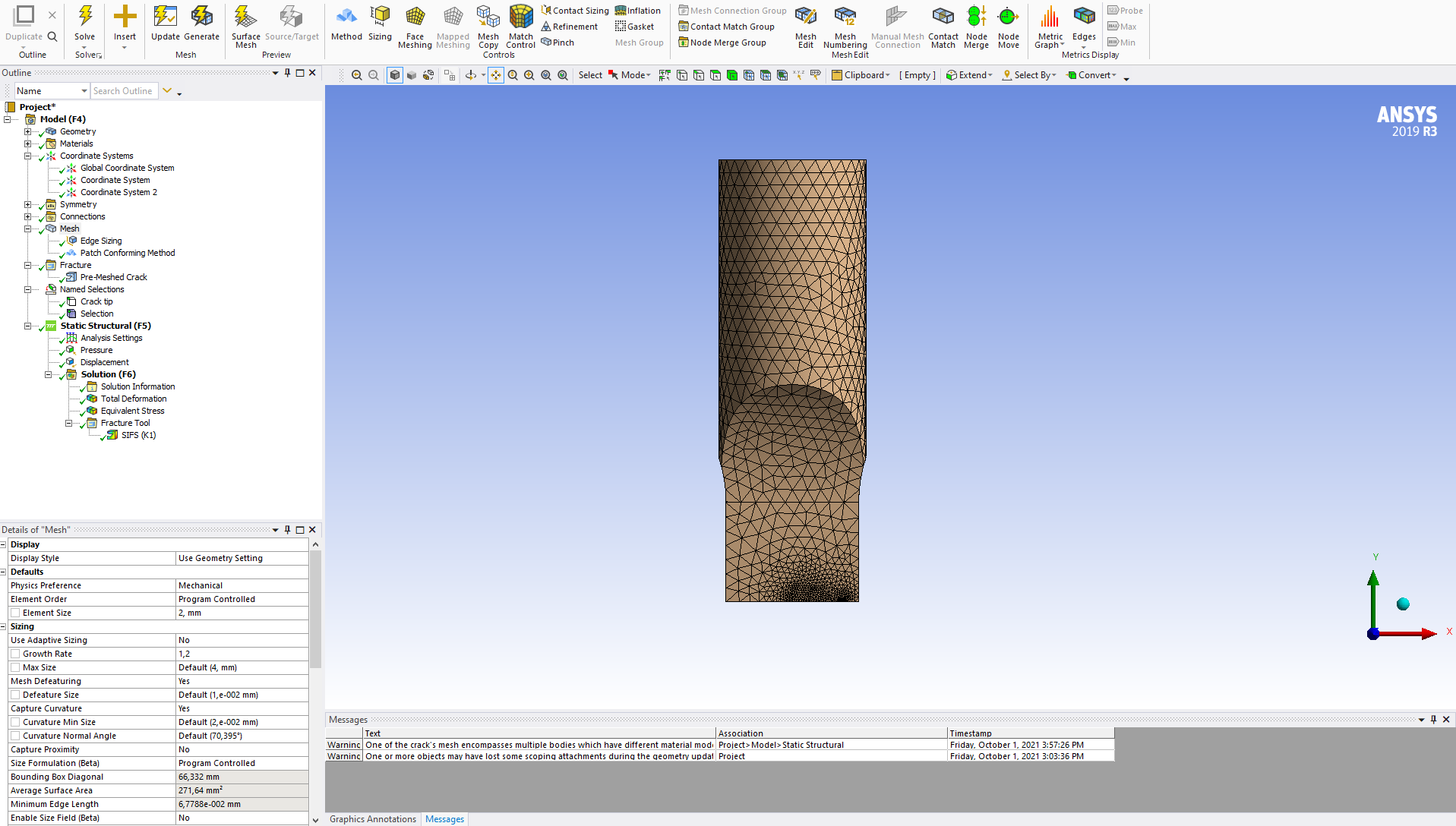 The SIF values are not changing according to crack length. However, the only problem is the SIF value is substantially large compare to analytical solution and also SIF from 2D model . ( I have already got the SIF for 2D and compared it with analytical solution and that seems correct results). I am really not sure what mistake i could be making here that is leading to high SIF. One results of SIF for three cases are below ( from 3D. from 2D, and analytical solution.
Notch length = 2.25 mm
Crack length = 2 mm
SIF(K1)_3D = 2030 MPa*mm^0.5
SIF(K1)_2D = 485 MPa*mm^0.5
SIF(K1)_Analytical solution = 496 MPa*mm^0.5
Could you please help me here. what could be the mistakes i am making here? Let me know if you need further information.
Thank you
Best Regards
October 13, 2021 at 10:45 amSubscriberHI Daniel,
So i was able to find the mistake i was making. I was applying 100 Mpa pressure in 3D model on top surface of the specimen, which lead to higher stresses (higher force reaction) at the middle rectangular section owing to smaller area than top round surface of the specimen. so, there was different stresses applied on 2D (100 Mpa) and 3D (250-300 Mpa) at middle of section ( specimen location with crack). Anyway, Now i have an another question.
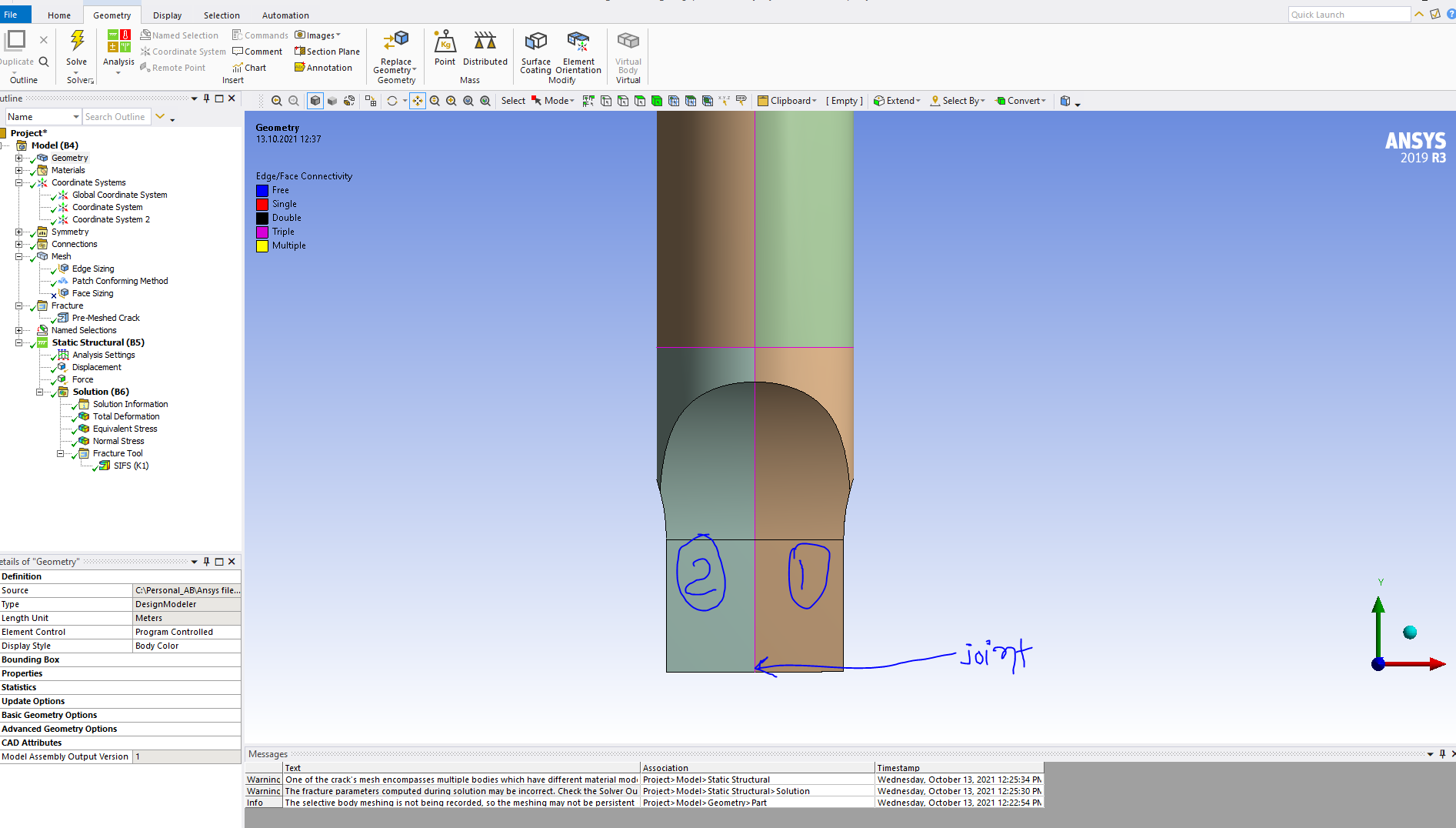
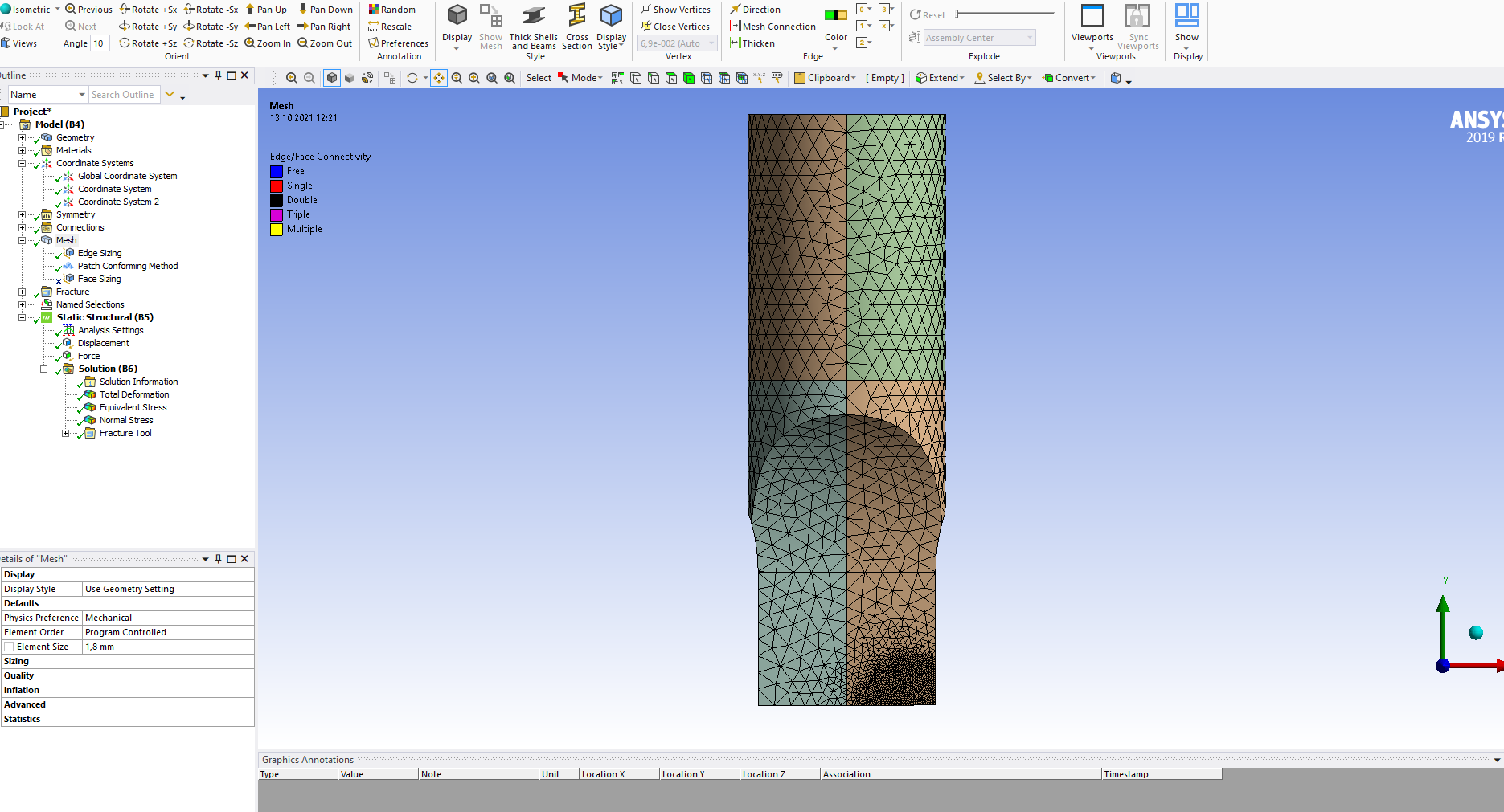
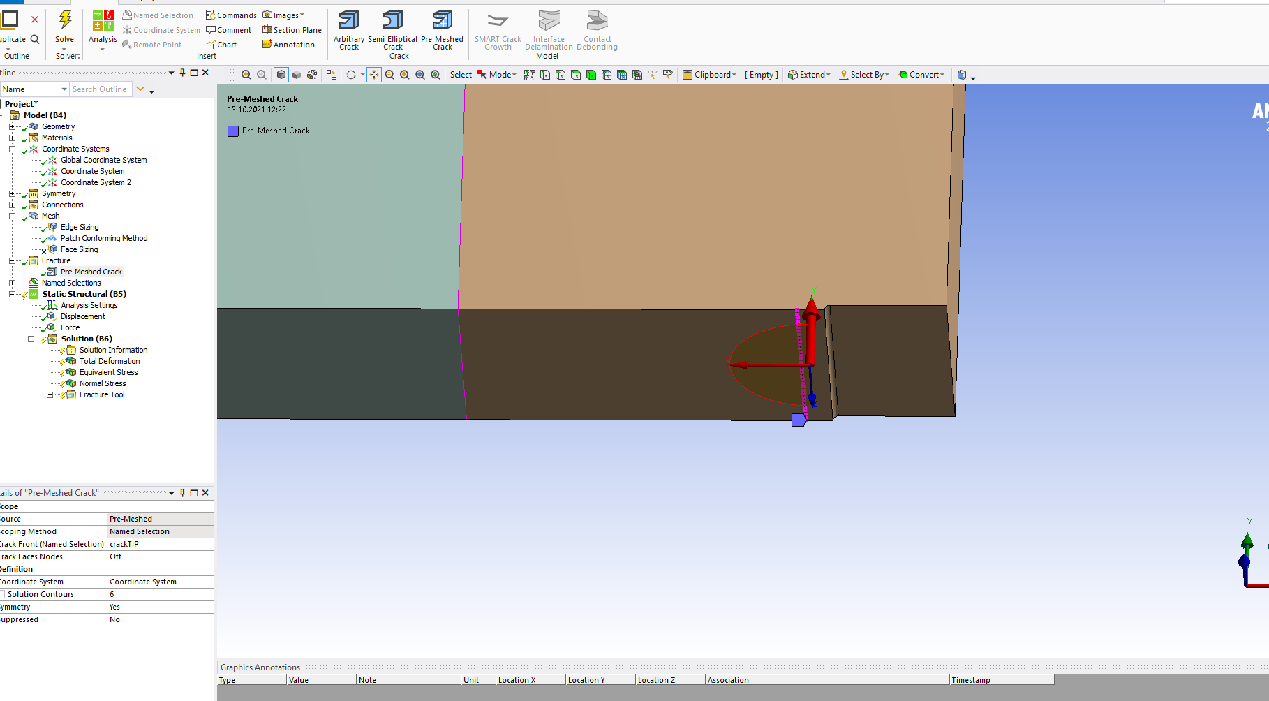
I now finding the SIF for 3D model joined with two different material as shown in below image.
Meshing
 Crack tip defining
 I am getting solution with warning that the Fracture parameters computed may be incorrect. I checked the solution and it says ,
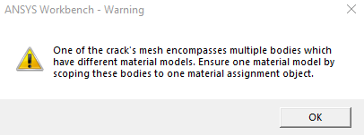
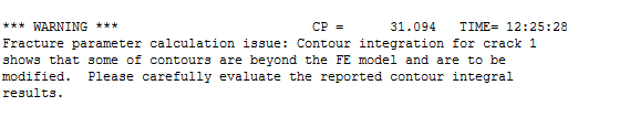 I do not know how to solve this error. i am not getting this error in another 3D model with one material. How can i resolve this error so i can be confident on the resulting values. however, SIF results are comparable to another 3D model. so i can just ignore it. But then again, when i find SIF for extended crack going into second material (long crack), i am getting the lower SIF then SIF for shorter crack and that makes me reluctant to just ignore the error. (second material has transverse isotropy and higher E than first material ) .
If you can also help me in understanding and solving below error, that would be helpful as well.
Thank you in advance for your inputs.
Regards
Viewing 3 reply threads- The topic ‘Determination of stress intensity in 3D model of SENT specimen.’ is closed to new replies.
Innovation Space Trending discussions
 Top Contributors
-
peteroznewman
 6520
6520 -
scabo
 1906
1906 -
Dennis Chen
 1463
1463 -
javat33489
 1310
1310 -
Shyam Prasad V Atri
1022
Top Rated Tags
© 2026 Copyright ANSYS, Inc. All rights reserved.
Ansys does not support the usage of unauthorized Ansys software. Please visit www.ansys.com to obtain an official distribution.
-


The Ansys Learning Forum is a public forum. You are prohibited from providing (i) information that is confidential to You, your employer, or any third party, (ii) Personal Data or individually identifiable health information, (iii) any information that is U.S. Government Classified, Controlled Unclassified Information, International Traffic in Arms Regulators (ITAR) or Export Administration Regulators (EAR) controlled or otherwise have been determined by the United States Government or by a foreign government to require protection against unauthorized disclosure for reasons of national security, or (iv) topics or information restricted by the People's Republic of China data protection and privacy laws.
