TAGGED: fdtd, lumerical, reflection, waveguides
-
-
June 19, 2021 at 11:17 am
ismailsarwar
SubscriberDear Lumerical Community,
I am designing a device which is using grating coupler. The Frequency domain field profile monitor is present on the top to capture the light. I was getting good modes but with quite low transmission efficiency. I stretched the top monitor on whole device and after simulation I saw transmission much stronger than grating coupler from the source directly to the upper monitor.
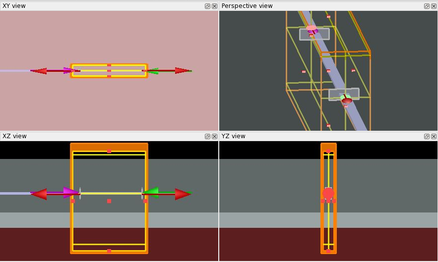
So, I reverted back and did simulation with just a simple waveguide having monitor on top in the air and also a monitor in the silicon substrate beneath. Here I also saw reflections, which I might have a guess, coming from the source. As ultimately I have to guide the light through the grating coupler, so I am very concerned about these reflections.
Any suggestions would be really appreciated. I have also attached the photos for the reference.
With Kind Regards
June 24, 2021 at 9:11 pmKyle
Ansys Employee
This might be due to the fact that the span of the ports is too small, so the modal field is truncated. There is more information on this issue in the "source span" section on this page: /forum/discussion/24201/ansys-insight-key-fdtd-simulation-settings/p1
Please try increasing the span of the ports in your straight waveguide simulation, and let me know if that helps.
July 1, 2021 at 12:44 pmismailsarwar
Subscriber
Thank you so much for your reply.
In the "source span" section on the page recommended it is written that:
"The source fields should be visualized to make sure they have decayed sufficiently at the edges of the source span (at an amplitude of10^3 to 10^4)."
I have understood from this line that if the fields are decayed such that we see only an an amplitude of10^3 to 10^4 then simulation settings should be fine. As from the fig.2 that I have shared above the scale is showing the highest red color field has the power of 0.000569. So, do you think this is already in the range as discussed in the shared article or the results from these monitors are not to be taken care off?
P.s.: I always visualize my mode field of source to see if perfect mode is present inside.
With Kind Regards
Ismail Sarwar
July 2, 2021 at 10:10 pmKyle
Ansys Employee
The page I linked is referring to the modal fields of the source/port, not the fields measured by a monitor at the edges of the simulation region. The amplitude of the field in your Fig. 1 and Fig. 2 is small, and some error is always expected in a simulation, but I would still expect these fields to be smaller for a straight waveguide, which should theoretically have no scattered field.
I thought it might be your ports causing this scattering, as there is nothing else in a straight waveguide to scatter the light. From your screenshots it looks like the port spans are about double the span of the waveguide, which generally isn't enough. This is why I think it might help to increase the span of the ports to reduce the injection error.
Viewing 3 reply threads- The topic ‘Reflections due to source / Input port’ is closed to new replies.
Innovation SpaceTrending discussionsTop Contributors-
5094
-
1830
-
1387
-
1248
-
1021
Top Rated Tags© 2026 Copyright ANSYS, Inc. All rights reserved.
Ansys does not support the usage of unauthorized Ansys software. Please visit www.ansys.com to obtain an official distribution.
-


