TAGGED: fdtd
-
-
June 13, 2021 at 2:49 pm
tsinghuaby
SubscriberThe cross polarization conversion efficiency is defined as “Simulated polarization conversion efficiency as a function of wavelength. This efficiency is defined as the fraction of the incident circularly polarized optical power that is converted to transmitted optical power with opposite helicity.”
Here, I used left-handed circularly polarized light as the incident light source to perform S-parameter analysis on the metasurface. How should I use the results of S-parameter analysis to calculate the optical power of incident light and the transmitted right-handed circularly polarized light, and then calculate the conversion efficiency?
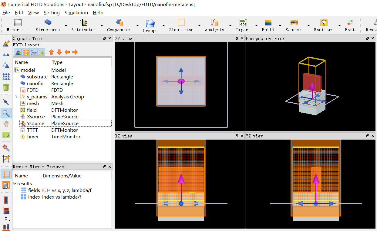
Below is my FDTD simulation configuration :
June 15, 2021 at 10:13 amtsinghuaby
SubscriberI really need your help! ƒÿöƒÿö
June 15, 2021 at 2:35 pmGreg Baethge
Ansys EmployeeHi Thanks for your post and apologies for the wait. Note we aim to reply within 2 working days and we do our best to reply as quickly as possible.
Regarding your question, the "s-params" analysis group calculates a result called "S_polarization", that will give the coupling information to the s and p polarizations. Alternatively, you can also use the polarization ellipse analysis from the object library.
That said, if this will give the fraction of coupling in the 2 polarizations and the phase information, allowing further analysis, I'm not too sure how to get the conversion efficiency. In the literature, the cross polarization conversion efficiency is often defined for linear polarization, where the input polarized along x can be converted into y polarization, for example. With this, I could see how to check if the transmitted or reflected fields are RCP or LCP, using the ellipticity analysis, for instance.
I found this publication, but I couldn't find any information on how the calculation is done!
June 15, 2021 at 3:40 pmtsinghuaby
SubscriberHi@greg_baethgeVery happy to receive your reply! Thank you very much for your reply!
The problem is this: What is incident on the metasurface structure unit is left-handed circularly polarized light, which is composed of an x-line polarized light source and a y-line polarized light source. Since the metasurface has a polarization conversion effect, the incident left-handed circularly polarized light will be converted into a part of right-handed circularly polarized light. To this end, we first need to obtain the x-polarized light and y-polarized light components after passing through the metasurface, and then use them to represent the outgoing right-handed circularly polarized light components, and then calculate the polarization conversion efficiency according to the definition.
In order to give you a better understanding of this problem, I have attached a related reference and marked the relevant parts in the literature. You can refer to it. I hope it will help us solve this problem! The specific problem I want to solve now is to use FDTD to double-track Fig. 1.F in this document.
Looking forward to your reply and help!ƒñùƒñùThank you so much!
June 16, 2021 at 3:15 pmtsinghuaby
SubscriberHi@greg_baethge
Do you have some calculation suggestions or calculation methods for this problem? I donÔÇÖt know if I have described the problem to you? I am also dumbfounded now!
June 17, 2021 at 10:46 amGreg Baethge
Ansys Employee
I'm still working on this. I discussed it with a colleague, I believe we have some ways to calculate this. I'll be able to give you further details on this calculation once we checked it, probably later today or tomorrow. Thanks for your patience!
June 17, 2021 at 10:55 amJune 18, 2021 at 1:12 pmGreg Baethge
Ansys Employee
Thank you for your patience! As I suspected, this calculation will rely on using the "S_polarization" result from the "S_params" analysis group. First, it will require 2 simulations. As discussed in Circular polarization and phase convention, we can reconstruct the circular polarization from 2 simulations, each with 1 source:
Source polarized along x
Source polarized along y
With these 2 simulations, we can then obtain RCP and LCP by combining the results. An important note, in the S parameter calculation, we apply a correction factor based on the refractive indices of the top and bottom material, this is so the S parameters of a planar structure match the Fresnel coefficient (see Metamaterial S parameter extraction). If you look at the analysis script, we have:
# Normalize S-parameters to source power
S11_Gn(i) = S11_Gn(i) * sqrt(R(i));
S21_Gn(i) = S21_Gn(i) * sqrt(T(i)) * (sqrt(refractive_index_1/refractive_index_2)); # correct amplitude if top/bottom substrates are different
S11_pol_Gn(i,1:2) = S11_pol_Gn(i,1:2) * sqrt(R(i));
S21_pol_Gn(i,1:2) = S21_pol_Gn(i,1:2) * sqrt(T(i)) * (sqrt(refractive_index_1/refractive_index_2)); # correct amplitude if top/bottom substrates are different
Where refractive_index_1 is the refractive index of the bottom material (where the reflection monitor is), and refractive_index_2, the one of the top material (where the transmission monitor is). For the polarization conversion efficiency, we need to remove this correction. So we will have:
Simulation 1 (polarization angle set to 0):
S_pol = getresult(sname,"S_polarization");
f = S_pol.f;
refractive_index_1 = real(getdata(sname+"::R_index","index_x"));
refractive_index_2 = real(getdata(sname+"::T_index","index_x"));
S21_x= S_pol.S21_Gn; # size = [length(f),2] (First column: s(y)-polarization component, second colum: p(x)-polarization component)
S21_x=S21_x/sqrt(refractive_index_1/refractive_index_2);
Simulation 2 (polarization angle set to 90):
S_pol = getresult(sname,"S_polarization");
S21_y= S_pol.S21_Gn;
S21_y=S21_y/sqrt(refractive_index_1/refractive_index_2);
With these 2 results, we can then build the response to a LCP and RCP input, using, for RCP, E_R = (E_x - 1i*E_y)/sqrt(2) and E_L=(E_x +1i*E_y)/sqrt(2) for LCP.
S21_L = (S21_x + 1i*S21_y)/sqrt(2);
S21_R = (S21_x - 1i*S21_y)/sqrt(2);
Finally, we can extract the LCP and RCP components in S21_L and S21_R:
S21_LR = (S21_R(:,1) + 1i*S21_R(:,2))/sqrt(2); # RCP input --> LCP output
S21_RR = (S21_R(:,1) - 1i*S21_R(:,2))/sqrt(2); # RCP input --> RCP output
S21_LL = (S21_L(:,1) + 1i*S21_L(:,2))/sqrt(2); # LCP input --> LCP output
S21_RL = (S21_L(:,1) - 1i*S21_L(:,2))/sqrt(2); # LCP input --> RCP output
Then, the conversion efficiency is given by abs(S21)^2, so you can get the conversion efficiency from RCP to LCP, etc.
Using this method, we got good agreements with Fig. 2e of Chen, W.T., Zhu, A.Y., Sanjeev, V. et al. A broadband achromatic metalens for focusing and imaging in the visible. Nature Nanotech13, 220ÔÇô226 (2018). https://doi.org/10.1038/s41565-017-0034-6
I hope this will help!
-
July 24, 2022 at 8:10 pm
roy.shuvajit
Subscriber@/forum/index.php?p=/profile/greg_baethge
If someone does this as you have mentioned, Finally, we can extract the LCP and RCP components in S21_L and S21_R:
S21_LR = (S21_R(:,1) + 1i*S21_R(:,2))/sqrt(2); # RCP input --> LCP output
S21_RR = (S21_R(:,1) - 1i*S21_R(:,2))/sqrt(2); # RCP input --> RCP output
S21_LL = (S21_L(:,1) + 1i*S21_L(:,2))/sqrt(2); # LCP input --> LCP output
S21_RL = (S21_L(:,1) - 1i*S21_L(:,2))/sqrt(2); # LCP input --> RCP outputIsn't S21_LR the same as S21_RR if we take abs(S21_LR)^2. Just +i and -i. Similarly, it is valid for LCP input. How are the transmission coefficients correct? Please reply. I am facing the same issues
-
November 29, 2022 at 7:18 am
xuanlunhuang20
Subscriberc1=a+1i*b, c2=a-1i*b, abs(c1)=abs(c2) if a and b are both real number. But now a and b are complex numbers.
-
June 18, 2021 at 3:47 pmtsinghuaby
SubscriberHi @greg_baethge´╝î
Thank you very much for your reply! Your reply was so timely, you saved me, hahaƒÿèƒÿè, thank you very, very much!
After carefully considering your suggestions, I benefited a lot! But I still encountered some problems.
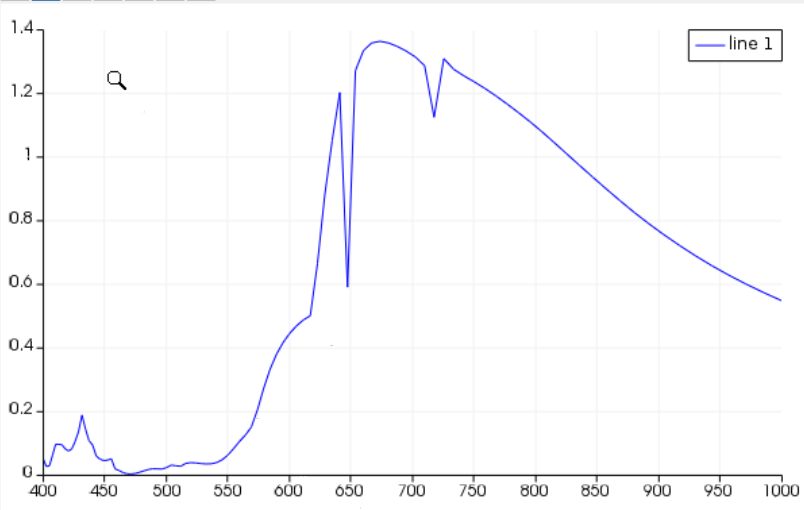
I used your calculation suggestion, but I still did not get the correct result. The calculation result I got is as follows:´╝êWhy does the calculation result exceed 1? ´╝ë
 The calculation script I used is as follows:
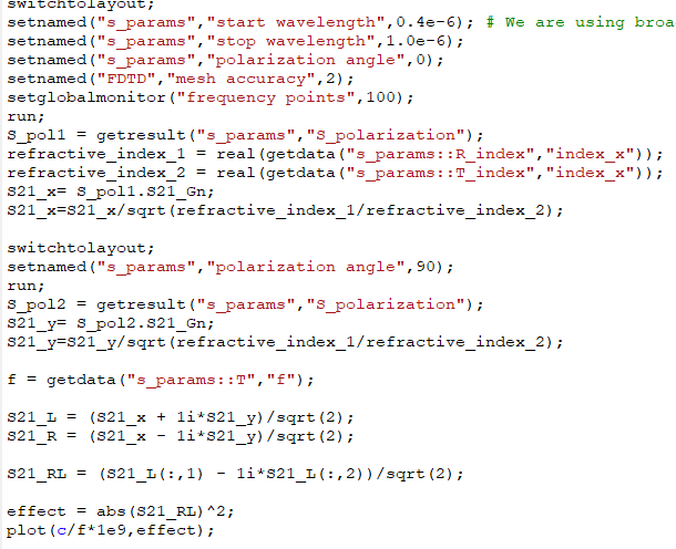
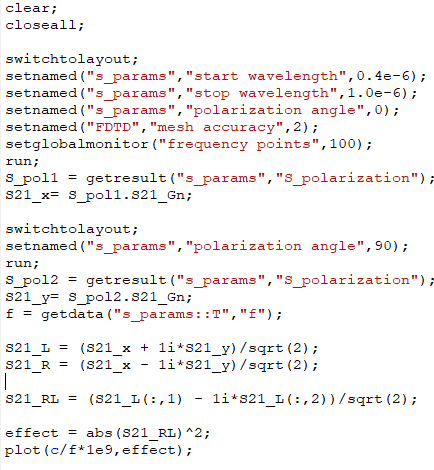 Some calculation formulas in the calculation script I used have changed. This is because I am using an improved version of the S-parameter analysis script, which has corrected the amplitude. The details are as follows: ´╝êFor the detailed script file, you can refer to the S-parameter analysis script used in the official metalen simulation routine. ´╝ë
 Later, I performed the calculation exactly according to your calculation script (still using the improved S-parameter analysis), but found that the calculation result is also different from the result in the literature. The result at the target wavelength is too large and the red shift occurs.
The specific results are as follows:
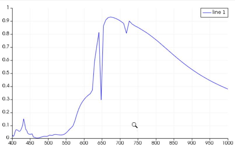
 I simulated the red curve in the literature.
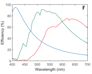 Is there a problem with my calculation?ƒÿöƒÿö@greg_baethge
Looking forward to your reply!
June 18, 2021 at 4:01 pmGreg Baethge
Ansys EmployeeYou're very welcome, Regarding your questions, in your first calculation, you didn't divide by sqrt(n1/n2) (the correction factor I mentioned), this can lead to abs(S)^2>1.
Regarding the difference with the literature, it is very difficult to say. They may have used a different method to calculate the conversion efficiency. Also, these result are dependent on the simulation settings, the material properties, etc. Some convergence testing might help to make sure the simulation is set properly.
June 19, 2021 at 3:42 pmtsinghuaby
SubscriberHi @greg_baethge´╝îThank you very much for your reply!
In the first calculation, the reason why I didn't divide sqrt(n1/n2) (the correction factor you mentioned) is because I found that this part has been corrected in the S-parameter analysis script. The details are as follows:
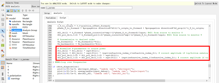 Why do we need to calibrate again in the calculation script? What is the physical mechanism of this correction? I am very confused about this.
greg_baethge´╝îyou mentioned earlier that you got results that are consistent with those in the literature. Can I see your results? According to your opinion,I carefully checked my simulation configuration, and I am roughly sure that there is no problem with it, so I wonder if there is a problem with my material parameters?If you use this method to obtain results that are almost the same as those in the literature, can you share with me the material parameters you used. I very much approve of the calculation scheme you provided, and I especially want to figure out the reasons for the discrepancies between my results and those in the literature. I hope you can help me solve this problem, thank you very much!
Looking forward to your reply!ƒÿèƒÿè
June 19, 2021 at 3:48 pmJune 21, 2021 at 11:30 amGreg Baethge
Ansys Employee
In the first calculation, the reason why I didn'tdivide sqrt(n1/n2) (the correction factor you mentioned) is because I found that this part has been corrected in the S-parameter analysis script. The details are as follows:
...
Why do we need to calibrate again in the calculation script? What is the physical mechanism of this correction? I am very confused about this.
Actually, dividing by the factor is to remove it in the S parameter. In the analysis group, the S parameters are defined so that for a planar structure they match with the Fresnel coefficients, defined according to the convention in D. R. Smith et al., "Electromagnetic parameter retrieval from inhomogeneous metamaterials", Phys Rev E 71, 036617 (2005). This is why we apply this correction factor. On the other hand, in the efficiency calculation, we need to get back to the fields' amplitude so we remove this correction factor.
Regarding the results I mentioned in my previous post, we ran the calculation corresponding to the orange curve in Fig 2e from the paper.
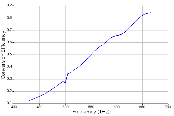 Our results show a similar trend, but the paper doesn't mention the material properties used in their calculations, which makes reproducing their plot quite difficult. Unfortunately, there is no real way to "guess" what materials were used. You can try with data from different sources, and see how they affect the results.
June 21, 2021 at 12:15 pmtsinghuaby
SubscriberHi @greg_baethge´╝îThank you very much for your reply!
Based on your reply, I figured out the first question.
Regarding the second question, the materials used are mentioned in the literature. The substrate uses SiO2 and the super-surface structural unit uses TiO2. greg_baethge, if you have time, you can try to calculate with this combination of materials to see if the results we get are consistent.
Do you have any good way to verify our calculation script? Ôÿ║´©ÅÔÿ║´©Å
Looking forward to your reply!
June 22, 2021 at 2:59 pmGreg Baethge
Ansys Employee
You're very welcome. When I was talking about the material, I meant the challenge is to know what material properties are used (ie the refractive index). For 1 material like TiO2, the data can be taken from the literature or be measured. For example, if you look at the refractiveindex.info website, you can find 3 different data for TiO2 as thin film. I didn't check, but the data can be slightly different and, therefore, lead to different results in the simulations.
Unfortunately, I can't think of any obvious way to verify the calculation. I do think the calculation makes sense, the remaining question is still whether they use a similar method in the paper or not...
June 23, 2021 at 8:37 amYanfeng_Wang
SubscriberHi @greg_baethge´╝î
In simulation2, when we change the polarization angle to 90, do we also need to change the phase of the source to 90 to obtain RCP or LCP?
June 23, 2021 at 1:21 pmtsinghuaby
SubscriberHi @greg_baethge´╝îThank you very much for your reply!
In the next experiment, I will continue to verify, I also think the calculation method is correct, because I used another method to get the same calculation result. If I have new progress, I will give you feedback. I hope we can always maintain good communication. Thank you very much for sharing, it really made me gain a lot.
June 23, 2021 at 5:06 pmGreg Baethge
Ansys Employee
Actually, we don't need to change the phase, this is taken care of when we combine the results of the 2 simulations, by the 1i factor for LCP, and -1i for RCP:
S21_L = (S21_x + 1i*S21_y)/sqrt(2);
S21_R = (S21_x - 1i*S21_y)/sqrt(2);
You're very welcome, Glad to be helpful. Keep us updated with your progress!
June 24, 2021 at 12:32 amJune 24, 2021 at 9:11 amYanfeng_Wang
SubscriberHi @greg_baethge,
I still have two questions about the calculation of the phase delay.
Based on the three topics related to the calculation of the conversion efficiency and phase delay of the meta-lens, I have my calculation script in the attached figure.
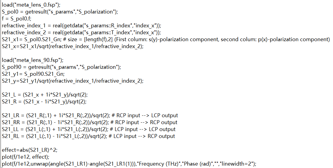 The first question is that when we do the phase calculation, do we need to keep the correction by using S21_x1 and S21_y1 in the script?
June 24, 2021 at 9:26 amYanfeng_Wang
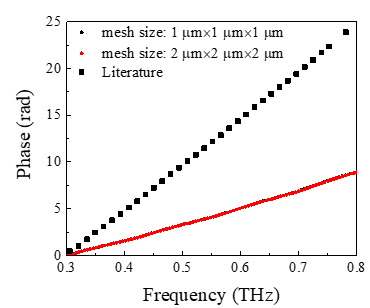
SubscriberThe second question is that in the other topic about the phase calculation, you mentioned the normalization of the resulting S parameters when performing the phase calculation.
 I cannot repeat the work in the literature which I think may be caused by the normalization of the S parameters. Can you help us figure out how to do the normalization in this case? Below shows the comparison of the results in the literature "Broadband achromatic metalens in terahertz regime" and my results. Thank you!
June 24, 2021 at 2:26 pmGreg Baethge
Ansys Employee
The first question is that when we do the phase calculation, do we need to keep the correction by using S21_x1 and S21_y1 in the script?
I don't think the correction factor will affect the phase calculation, as it is just a real number that is used.
I cannot repeat the work in the literature which I think may be caused by the normalization of the S parameters. Can you help us figure out how to do the normalization in this case? Below shows the comparison of the results in the literature "Broadband achromatic metalens in terahertz regime" and my results. Thank you!
When we calculate the response for a circular polarization, the normalization is done by the sqrt(2) factor. Regarding the plot, if this is the phase at the output of the metamaterial, you should use angle(S21_L) or angle(S21_R) as they correspond to the S parameter for a LCP (or RCP) illumination. It's not clear to me what the data from the literature is.
June 27, 2021 at 7:03 amYanfeng_Wang
SubscriberHi @greg_baethge,
If I use angle (S21_L) or angle (S21_R), I can get two curves corresponding to the s(y)-polarization component or p(x)-polarization component. How can I know the overall phase delay with the two components together?
Thank you!
June 28, 2021 at 6:15 amtsinghuaby
SubscriberHi @greg_baethge I contacted the author of the literature and obtained the properties of the material they used, but I still couldn't get consistent results with them. In the process of discussing with them, they mentioned that the result of the method we used would indeed be larger than theirs. The following is their specific response.

 What do they mean by "the first order diffraction efficiency of a Berry-phase grating"? How to use this method to calculate conversion efficiency?
Thank you!Looking forward to your reply!
June 28, 2021 at 3:51 pmGreg Baethge
Ansys Employee
Actually, S21_L and S21_R are already combinations of the s and p polarization, as I mentioned in a previous post.
I have to admit I'm not familiar with this at all. I'll try and check with my colleagues. It's not too clear what they mean. Maybe they used the Berry phase grating diffraction efficiency as the reference, to calculate the conversion efficiency.
June 29, 2021 at 12:39 amYanfeng_Wang
SubscriberHi @greg_baethge´╝î
We have two columns in S21_x and S21_y (First column: s(y)-polarization component, second column: p(x)-polarization component). Thus, after constructed the response to an LCP and RCP input, in S21_L and S21_R, we still have two columns corresponding to the s(y)-polarization component and p(x)-polarization component. If I use angle (S21_L) or angle (S21_R), I can get two curves. How can I know the overall phase delay of the light instead of the phase delay of the x- or y- polarization component?
June 29, 2021 at 8:28 amtsinghuaby
SubscriberHi @greg_baethge Thank you very much for your reply!
I think we can try to calculate the first order diffraction efficiency of Berry phase grating to observe the result.
How should the first order diffraction efficiency of Berry phase grating be calculated? What is the difference between this calculation method and our previous calculation method?
greg_baethge, what more information do you need to get? I can ask the author again.
June 29, 2021 at 11:25 amGreg Baethge
Ansys Employee
My bad, thanks for catching this! The S parameter analysis group returns 2 results, S and S_polarization. In this discussion, we've been using S_polarization as it gives the 2 components' contribution. In your case, you need to use S instead, to get the "global" response for a RCP or LCP. The idea will be the same: you calculate S for both polarization, and then combine the 2 S21 results.
June 29, 2021 at 11:37 amGreg Baethge
Ansys Employee
The grating order efficiency can be calculated using the same script commands we use in the S parameter calculation, although we may not need the polarization information, so grating could be enough.
As I mentioned, we use the grating projection to calculate the S parameters. However, the grating projection will only return the information relative to the power in each grating orders, while the S parameter will also include the phase information. As I said, it's not clear to me what they calculated, if they use the Berry phase grating as a reference or how they got the conversion efficiency.
June 29, 2021 at 12:53 pmtsinghuaby
SubscriberHi @greg_baethge I have some ideas about their calculation methods. But I have to confirm a few questions with you first.
Is the S-parameter analysis we use derived based on grating transmission? Does T_Gn return the transmittance of zero-order diffraction?
I think what the author meant is: there are multiple diffraction orders in the light after passing through the metasurface, but only zero-order diffraction is needed (he mentioned first-order diffraction, and I doubt it here because the energy after passing through the metasurface It is mostly focused on the zero order), but the cross polarization conversion we now calculate is for all transmitted light, which includes each diffraction order. So, I guess they should multiply the zero-order diffraction efficiency in their calculations.
What do you think?
-
August 29, 2023 at 12:20 pm
xiaofei.xiao15
SubscriberHi, did you find a way to calculate the same results as the paper shows? I am also struggling with it. thanks
June 30, 2021 at 4:17 pmGreg Baethge
Ansys Employee
You're correct, the S parameter calculation is based on grating projection. In the analysis setup, we specify which grating order we will use:
 In most (if not all) cases, we use the 0th order. In the results calculated by the analysis group, the suffix "_Gn" indicates the result corresponds to that selected order. So T_Gn is the fraction of power transmitted to the specified order, while T is the total transmission. The S parameters are only calculated from the selected order.
In the efficiency calculation, we use the S parameters calculated at each polarization. So for each polarization, we only consider the 0th order as well. In any case, in the device we used from the paper, T and T_Gn are equal, meaning there no power in higher order.
February 11, 2022 at 3:41 amFebruary 11, 2022 at 4:20 amGuilin Sun
Ansys Employee这个帖子是英语,请你写英文。或者在中文论坛另外提问。
February 11, 2022 at 4:22 am1766756937
SubscriberÕÑ¢þÜä´╝îÞ░óÞ░óµé¿þÜäµÅÉÚåÆ´╝ü
February 11, 2022 at 4:24 am1766756937
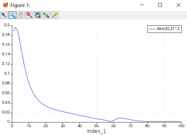
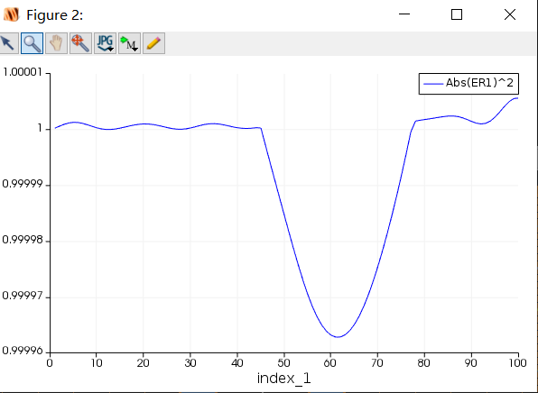
SubscriberHi @greg_baethge, I am also studying conversion efficiency. I am currently in the new stage, AND I have read your discussion and the previous discussion. I would like to ask you some questions about calculating conversion efficiency scripts.My idea is as follows: First, I hit the light from + Z to -z, and set the light to ER, which does not pass through the hypersurface, and EL, which does not pass through the hypersurface, as shown below
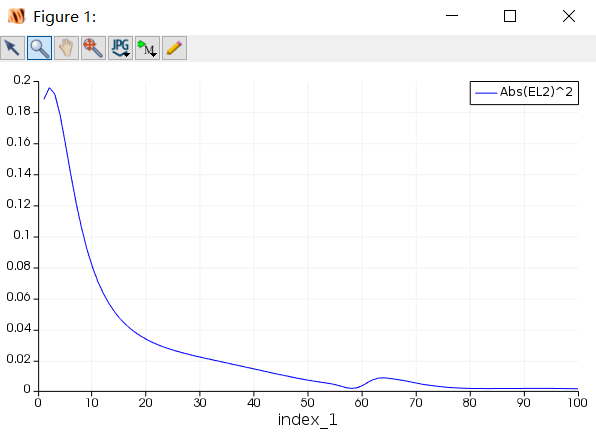
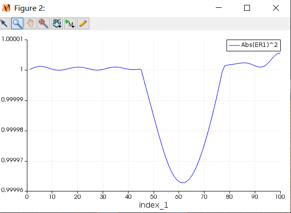
There is no relevant calculation formula for conversion efficiency in the literature, I would like to ask how to call the ER EL strength calculated by the previous script, shall we create a new script?Thank you for your answer!
February 14, 2022 at 12:27 pmGreg Baethge
Ansys Employee
I'm not too sure to understand what you mean by ER and EL and what is in the plots you attached. Could you clarify? In this discussion, we use the S parameter analysis to calculate the conversion efficiency between right-handed and left-handed circular polarizations. 2 simulations are required to get the orthogonal polarizations, and a script is used to combine the results to get RCP and LCP, and their conversion efficiency. The basic idea behind how to get circular polarization is detailed here and the S parameter extraction here.
February 19, 2022 at 5:08 am1766756937
SubscriberSorry for not replying to you in time!Sorry again!I'm sorry I couldn't articulate my problem.The model I have built has been verified and the previous post you discussed, I have not gone through the supersurface results have been normal, close to one.Then I read your post. I will tell you my thoughts and you can see where there are mistakes.I should make two models, one light source in each, and then the polarization Angle is 0, the other 90.And then does the phase have to be set?Maybe you just need to keep the Settings in the original file.Then converting the efficiency script only needs to run in one of the files, and I used the script from the previous post to calculate.Am I on the right track?Thank you for your reply and answer!
February 19, 2022 at 5:58 amFebruary 19, 2022 at 7:55 amFebruary 22, 2022 at 10:07 am1766756937
SubscriberI am looking forward to your reply. I'm just getting started´╝îI really want to know how to combine the results of two simulations.
February 23, 2022 at 1:51 pmGreg Baethge
Ansys Employee
My apologies for the delayed response, I'm glad you could solve the issue. As it may help other users, could you let us know what was causing the discrepancy with the literature?
Regarding the script, it does what I described in my previous post:
We run the simulations with orthogonal polarizations and extract the S parameters S_pol1 and S_pol2 (respectively for a source with polarization angle at 0 and 90). S_pol1 and S_pol2 have the S parameters for both polarization s and p (output polarization),
From S_pol1 and S_pol2, we calculate the response for RCP and LCP (S12_R and S12_L). The phase difference is introducted by the 1i and -1i factors
Then we calculate the conversion efficiency by combining the s and p polarizations from S12_L and S12_R in the same way as above
I hope this will help!
February 24, 2022 at 3:20 am1766756937
SubscriberThank you very much for your reply, which is very helpful to me.As for the solution to my problems, I added mesh refinement, added mesh and adjusted parameters, and then got the results similar to those in the literature.I still have problems to solve, and I hope to discuss them with you. First, the conversion efficiency between me and the literature is different, is that the reason for the model parameters?Second: the figure in the literature is concave at 650nm, but mine is not. Is this also due to the model, or is it related to the position of the monitor and light source?Looking forward to your reply!
February 24, 2022 at 5:08 pmGreg Baethge
Ansys Employee
Thanks for providing this information, I'm sure it will be valuable for other users. As for the remaining discrepancies, it is difficult to say, but reproducing results from a paper is always tricky: most of the time, the simulation settings are not fully disclosed. They may also use a different way to calculate the conversion efficiency.
At the end, you can run some convergence testing to make sure the simulation is set properly (see this page). I don't think the position of the monitor and light source will affect much. The calculate is done using grating projection. One thing though, the calculation takes into account the position of the source and monitor to get the phase correctly. This implies you have to properly set the position and span of the metamaterial (in the analysis tab) when calculating the S parameters.
-
July 23, 2022 at 7:11 am
roy.shuvajit
SubscriberHi,
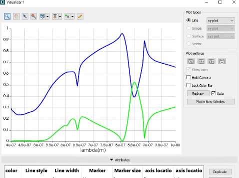
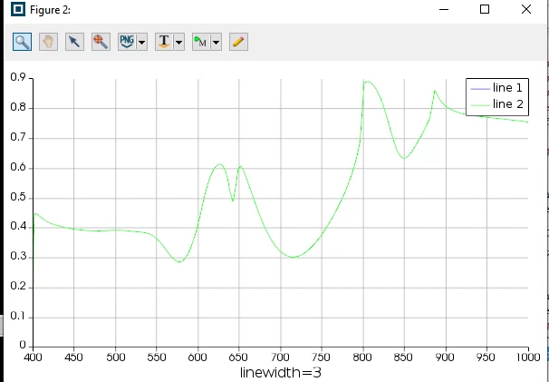
I am just following the code in the threads. This is the actual transmission reflection (blue: reflection, green : transmission) of my structure.
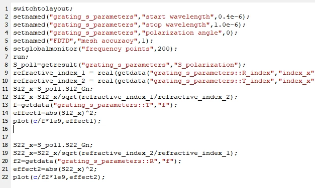
Now I am doing the s-parameter analysis to verify. Later I will check for RCP /LCP conversion for different structures. The transmission as I have followed is coming using the code:
The transmission is more or less ok. The amplitudes are different because I am using (abs)^2. The transmission:
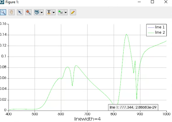
I have modified it for reflection mode dividing n2/n1 since the amplitude was coming to 4,4.2 (>1). The dips are not matching with the normal source and monitor reflection. This is the reflection:
can you help me in sorting out this?
February 27, 2022 at 7:12 am1766756937
SubscriberThank you very much for your answer. I will be well to understand!
April 18, 2023 at 6:10 pmRyu Jiwon
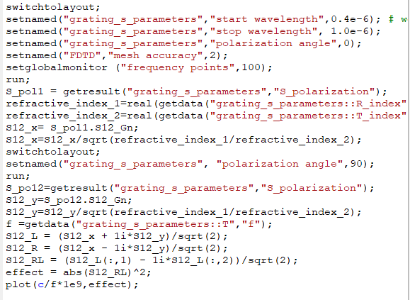
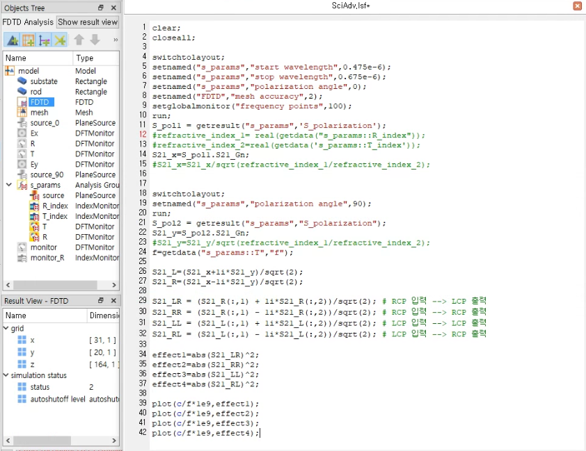
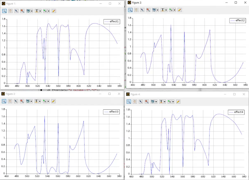
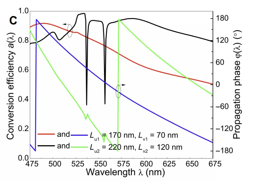
SubscriberI wrote the script with the help of the previous questions, but the graph is different from the paper.
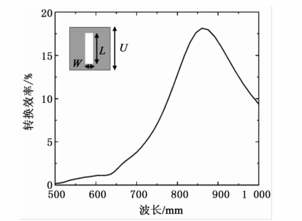
I want to plot the conversion efficiency graph when the rod size is l=220nm and w=120nm.
The paper I refer to is https://www.researchgate.net/publication/348888528_Bandwidth_Unlimited_Polarization-Maintaining_Metasurfaces.
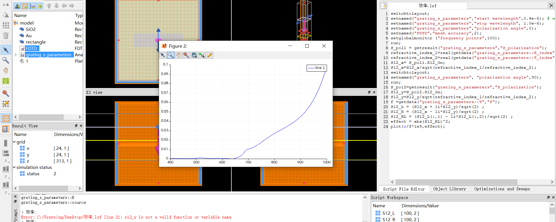
This is a picture of a script and a plot I wrote.
Below is a picture of the plot in the paper
Viewing 44 reply threads- The topic ‘Questions about the calculation of the cross-polarization conversion efficiency of metasurface’ is closed to new replies.
Innovation SpaceTrending discussionsTop Contributors-
4602
-
1510
-
1386
-
1209
-
1021
Top Rated Tags© 2025 Copyright ANSYS, Inc. All rights reserved.
Ansys does not support the usage of unauthorized Ansys software. Please visit www.ansys.com to obtain an official distribution.
-

