

-
-
June 9, 2021 at 4:37 pm
Sara91
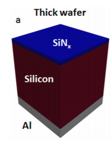
SubscriberI am trying to simulate the absorption of silicon with certain thicknesses, with and without surface texture. I started with just flat silicon with thickness 10 um on top of glass.
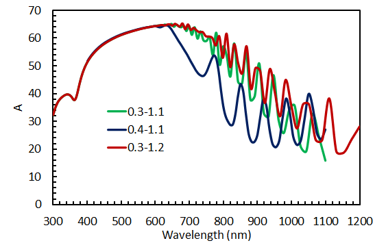
First, changing the wavelength range changes the absorption spectrum (as in the figure below: the legend indicates the wavelength range in um). I understand that changing the min wavelength will change the mesh, but how would I know which is more accurate? I did convergence tests as in this link (https://support.lumerical.com/hc/en-us/articles/360034915833-Convergence-testing-process-for-FDTD-simulations) but nothing seemed to make a difference in the results.
June 9, 2021 at 6:19 pmGuilin Sun
Ansys EmployeeFirst, about change of wavelength: When your starting or stop wavelength changes, not only the mesh size may change, but the material fitting will also change. This means you may simulate different set of material data since fitting range is changed and Maxwell Equations only know the permittivity. I would suggest that you only simulate the spectrum range you are interested in, no need to change the wavelength.
As for the absorption, now you are simulating a cavity not a bulk material, so the absorption will not be what you may think as long as the imag(eps) is not exactly zero.
Second, if the substrate is not lossy, or the loss is very small compared with Silicon, you can use A=1-R-T to get accurate absorption, provided that the simulation runs long enough and autoshutoff min is small enough in order for the DFT monitor to get correct frequency-domain result. The DFT monitor uses Fourier Transform so any truncation of the signal will lead to errors.
You do not need to place the monitor exactly on the interface.
Please make sure the substrate extends outside of periodic BC (similarly Si) in periodic direction and outside of PML in the light propagation axis.
June 9, 2021 at 9:40 pmSubscriberI checked the material fitting and it was similar in both cases. In any case, I am interested in the wavelength range from 0.3 to 1.2 um so I will stick with that.
Regarding the permittivity, the imaginary part is actually zero for the long wavelength range.
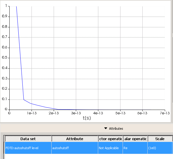
The simulation does run to autoshutoff. I am not sure exactly what you mean by "autoshutoff min is small enough" . This is how the autoshutoff level looks like:
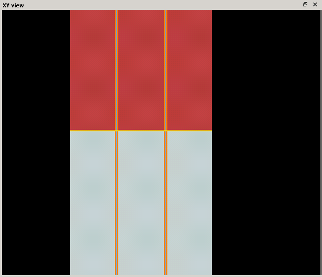
 Both the silicon and the glass substrate, as well as the monitors extend beyond the periodic boundary condition. this is an image of the interface:
I also tried to put the transmission monitor slightly below the interface (into the glass substrate) but it did not make a difference in the results.
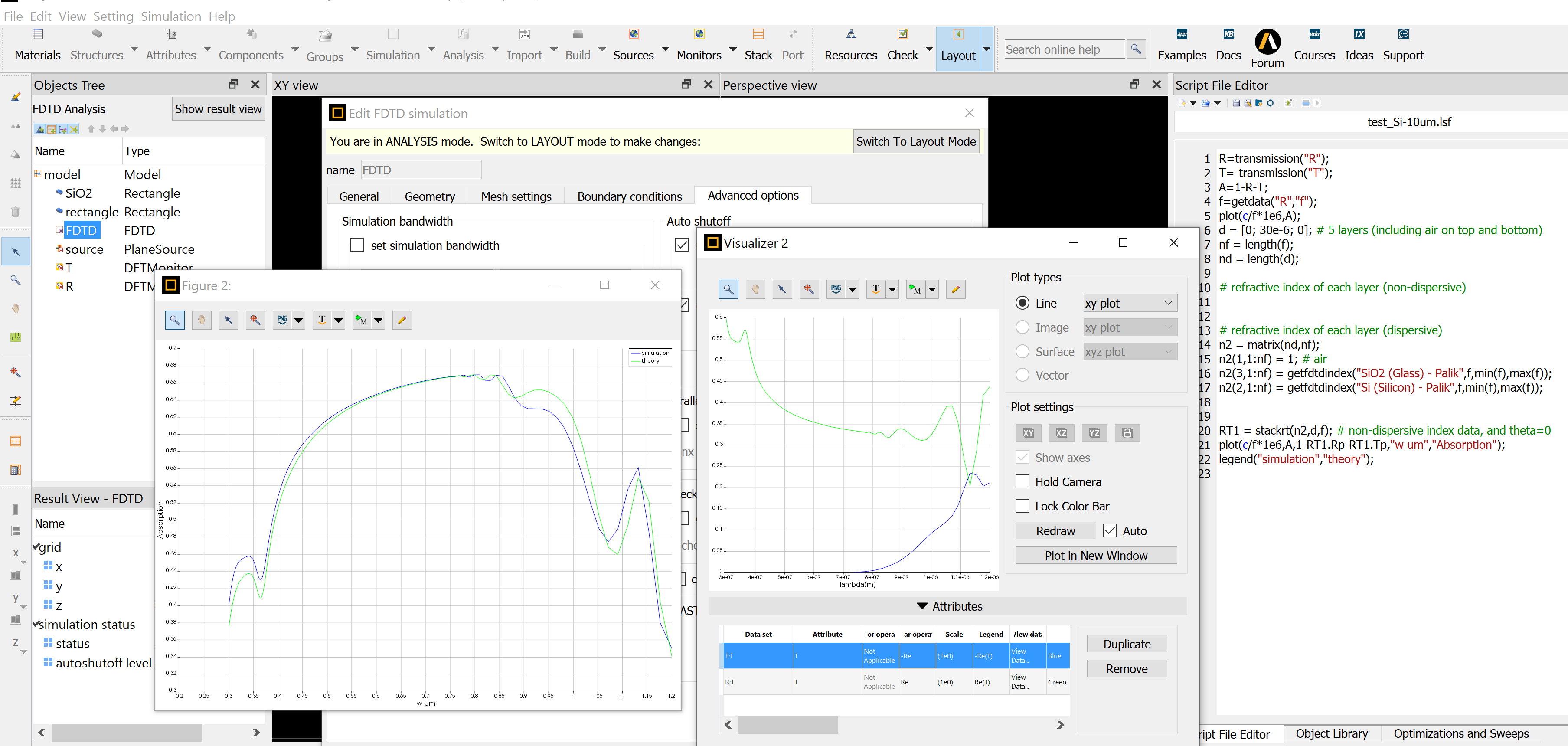
June 9, 2021 at 10:31 pmAnsys EmployeeI would suggest that you use stackrt to get the theoretical value and compare.
I set up a simulation file by use of your data, and got
Please make sure the simulation time is long enough that the simulation terminates before reaching 100%.
June 10, 2021 at 6:53 pmSubscriberMy simulated absorption is almost identical to yours. So at least for now, I am more confident in my simulation file/parameters.
I still have some problems with the results. I want to study a certain texture as a function of c-Si thickness, but first doing my calculations for flat silicon with various thicknesses. When I increase the silicon thickness to, for example, 30 um, both the reflection and transmission (especially the transmission) decrease significantly and more than expected. for example, the transmission becomes less than 20% in the NIR. This is not what you would expect from only a 30 um c-Si piece and does not agree with my measurements. I am wondering if you have some ideas in that regard.
Thanks.
June 10, 2021 at 8:35 pmAnsys EmployeeThis is most likely due to insufficient simulation time. Please significantly increase the simulation time, eg, 10 times or more, and let the autoshutoff min to terminate the simulation, and less than , say 95% in the Progress status. After simulation you can check the log file if you do not watch the simulation progress.
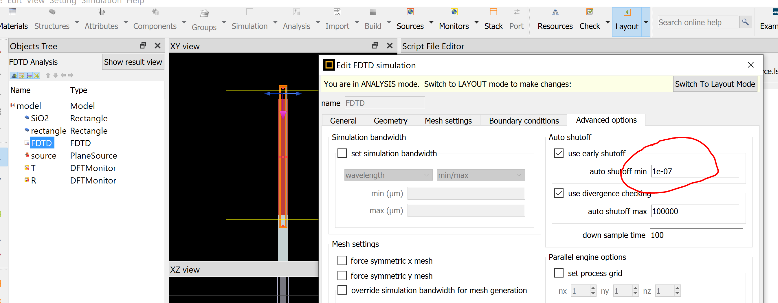
June 10, 2021 at 11:10 pmSubscriberI increased the simulation time from 3000 fs to 50,000 fs and the autoshutoff min from 1e-7 to 1e-10, but the results are the same in all cases and in all cases the simulation is terminated by the autoshutoff criteria (FDTD status is 2 and the log file indicated that "Early termination of simulation, the autoshutoff criteria are satisfied."
June 11, 2021 at 2:30 pmAnsys EmployeeHI, I used autoshutoff min 1e-7, simulation time 1e+6fs (too long,. You can use 1e+5fs), and got reasonable agreement with theory:
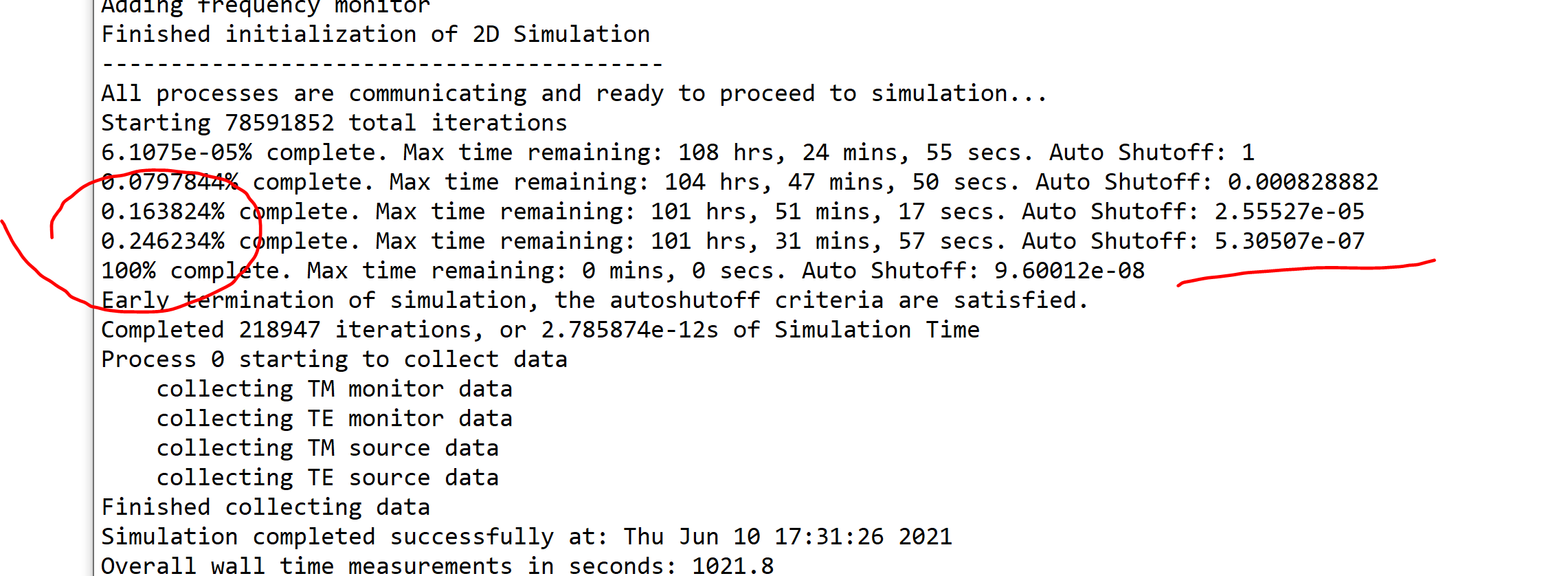
So your simulation time is not long enough!
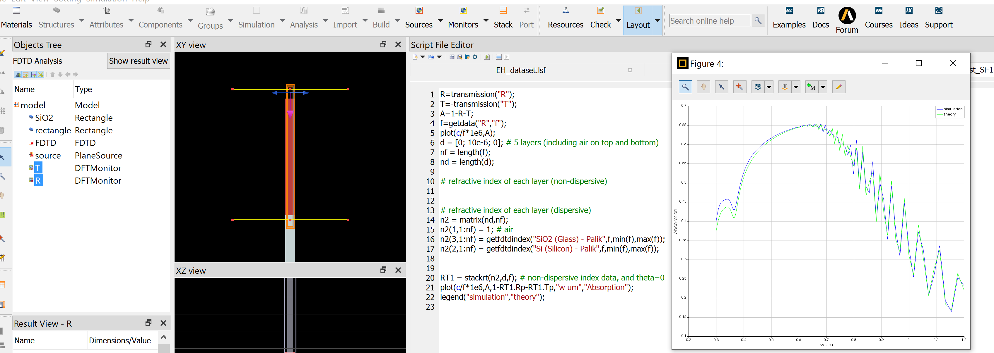
June 11, 2021 at 2:55 pmSubscriberThese results are actually very similar to what I have:
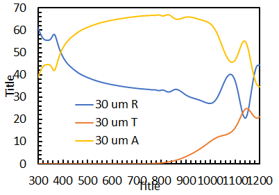
However, I still think there is an overestimation of the absorption in the long-wavelengths here.
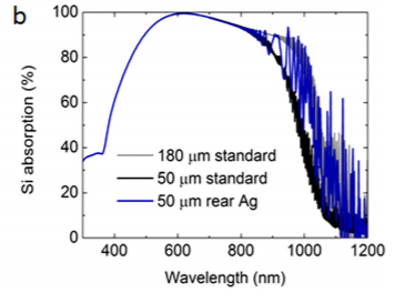
For example, in this paper (also using Lumerical: https://www.ncbi.nlm.nih.gov/pmc/articles/PMC4018607/pdf/srep04939.pdf) the absorption of 180 um of silicon (with back reflector) is zero at 1200 nm. So it is unclear to me why I have this high absorption at long wavelengths.
From the paper:
June 11, 2021 at 3:55 pmAnsys EmployeePlease note that for a cavity, its performance strongly depends on the cavity length and the mirrors. In the example you give, it has AL and SiNx layers as mirrors. Do you know their thickness? If you know, please use analytical method first.. I have verified my simulation result with this analytical method. We need to assure the result with solid theoretic base.
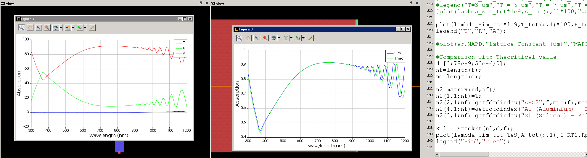
June 11, 2021 at 5:25 pmSubscriberThe SiN thickness is 75 nm and I put the bottom PML boundary through the back aluminum. I compared the Abs to the analytical absorption and they do agree (as in the screen shot below). But still the absorption is very high in the NIR.
June 11, 2021 at 7:17 pmAnsys EmployeeIt will be difficult for me to answer why the NIR region has high absorption. However as you have verified using theoretical method, I would suggest that you trust the theory. Do they use Al as substrate or it is part of the cavity? I would suggest that you only use analytical stackrt to justify your speculation. You can also find a formula from text book to do your own calculation.
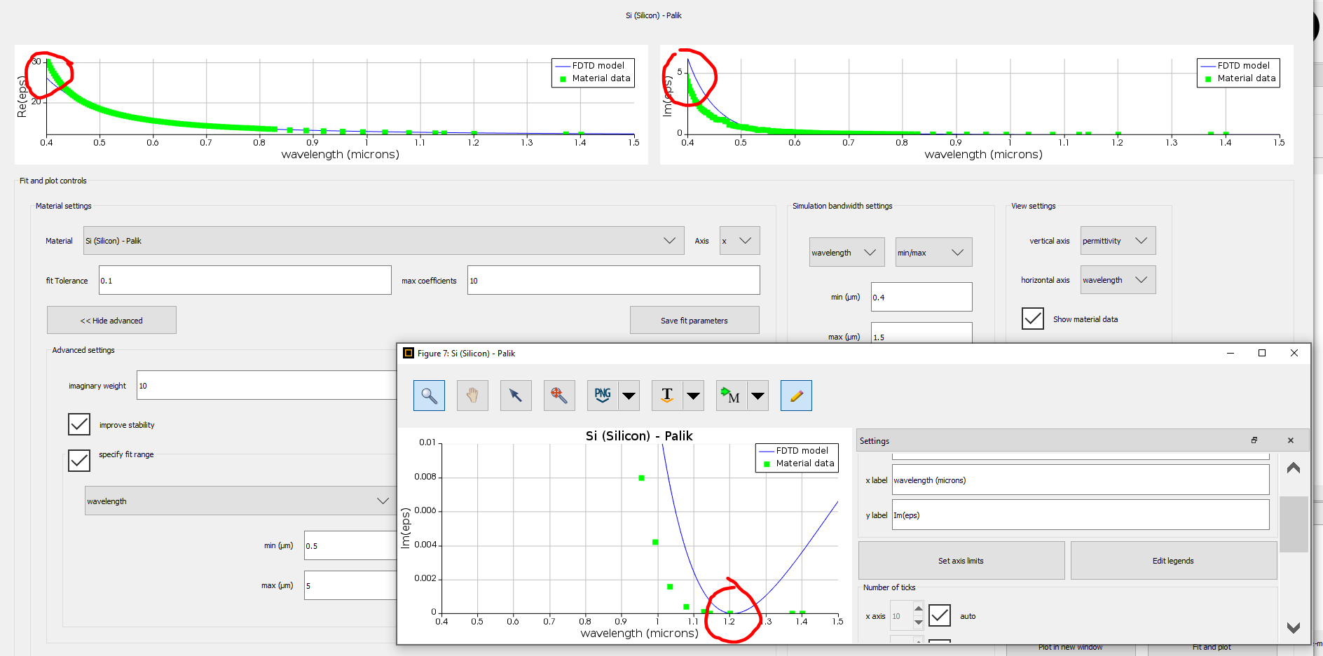
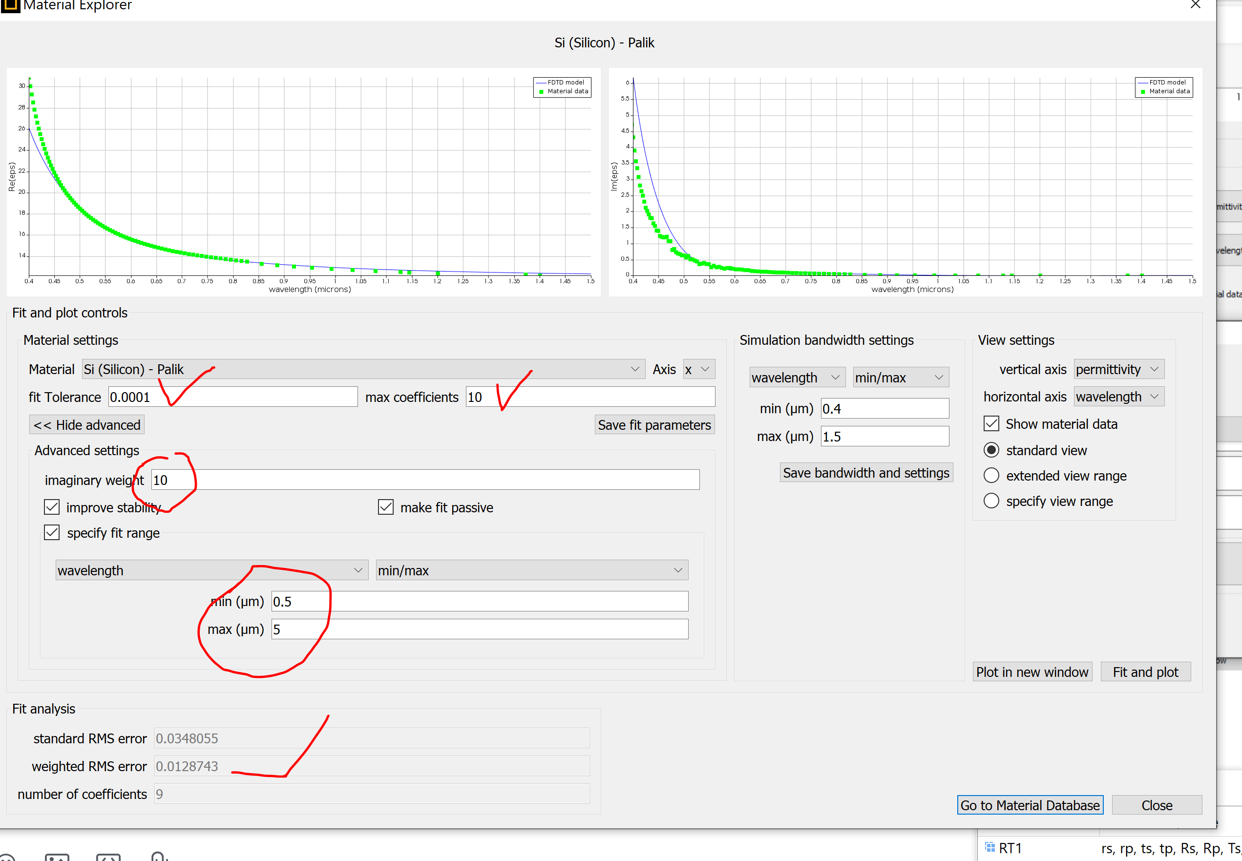
June 15, 2021 at 11:09 pmAnsys EmployeeMy colleague @Kyle Johnson reminds me that, the higher than expected absorption may come from the material fitting model, where from the experiment the imaginary part of permittivity is practically zero. However the material fitting gives small yet non-zero values. You can play around for the material fitting parameters and try to find a better model. I found it is very difficult to get zero without sacrifice the overall fitting accuracy in this broadband. Depending on your specific goal, you may choose fitting parameters to stress the importance of the infrared regime, by specifying the fitting wavelength range and the imaginary weight:
June 16, 2021 at 1:47 pmSubscriberHello,
I did what you recommended for the material fitting and it does make the results better in the long wavelengths range. However, as expected, it sacrifices the accuracy at short wavelengths. I understand that I am trying to simulate a very broadband range at once, do you think it is a good idea to split the simulation into two wavelengths region? for example, one simulation from 300 to 800 um and one from 800 um to 1200 um? I tried to do something like this previously, but I was encountered by the problem I was talking about in my first post (i.e. I get different results when I change the wavelength range).
June 16, 2021 at 4:00 pmAnsys EmployeeYou can do so but as mentioned before, if the bandwidth for simulation is not fixed, then the result is not continuous, since the material property and the mesh accuracy is not the same, But you should not get the result similar to the first post, as you will have 2 or more simulation begin and stop wavelengths. For example, you can simulate 0.3~0.7um and 0.7~1.2um. The only drawback is at 0.7um the result is different, due to known reason. So in many cases there is always a kind of compromise that you can choose to alleviate some issues but create other issues. I would suggest that you can fix the mesh generation bandwidth:
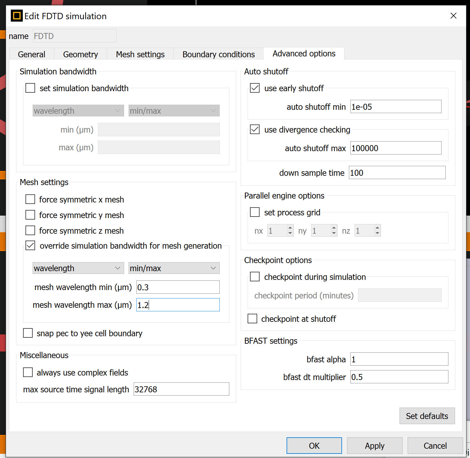
this can make sure the mesh is the same, so to leave only the fitting that causes such discontinuity. Sometimes such discontinuity can be small.
June 17, 2021 at 3:18 pmSubscriberI tried it manually (dividing it into two wavelength range) and the results look good so far, and fixing the wavelength for the mesh as you suggested helped to make the discontinuity very small.
I am trying to do that now via a script so that everything is automated and the results are combined together. the only thing missing is specifying the fit range in the material explorer using the script (I want to specify the fit range in the first half of simulation to be from 0.3 to 0.7 and for the second half to be from 0.7 to 1.2). Could you tell me what is the command to use to set the "specify fit range" in the "advanced settings" in the material explorer?
I tried to find it on the web but could not find anything so far. Thanks.
June 17, 2021 at 3:36 pmAnsys EmployeeIt is "setmaterial": https://support.lumerical.com/hc/en-us/articles/360034409654-setmaterial-Script-command
You can find all the parameters you can set by script by:
?setmaterial("Au (Gold) - Palik");
name
mesh order
color
anisotropy
type
tolerance
max coefficients
make fit passive
improve numerical stability
imaginary weight
specify fit range
wavelength min
wavelength max
frequency min
frequency max
sampled 3d data
However, most of the parameters from the material database is write-protected. In order to modify them, you have to create a copy of the material first; then make "specify fit range" to be 1:
copymaterial: https://support.lumerical.com/hc/en-us/articles/360034930033-copymaterial-Script-command
copymaterial("Au (Gold) - Palik");
setmaterial("Au (Gold) - Palik Copy 1","specify fit range",1);
you can try to set all other parameters.
Please try. If you have other questions regarding the script, please write a sperate post since it is not the subject of this topic.
Viewing 16 reply threads- The topic ‘Simulation with broadband wavelength range’ is closed to new replies.
Innovation Space Trending discussions
 Top Contributors
-
peteroznewman
 6269
6269 -
scabo
 1906
1906 -
Dennis Chen
 1457
1457 -
javat33489
 1308
1308 -
Shyam Prasad V Atri
1022
Top Rated Tags
© 2026 Copyright ANSYS, Inc. All rights reserved.
Ansys does not support the usage of unauthorized Ansys software. Please visit www.ansys.com to obtain an official distribution.
-


The Ansys Learning Forum is a public forum. You are prohibited from providing (i) information that is confidential to You, your employer, or any third party, (ii) Personal Data or individually identifiable health information, (iii) any information that is U.S. Government Classified, Controlled Unclassified Information, International Traffic in Arms Regulators (ITAR) or Export Administration Regulators (EAR) controlled or otherwise have been determined by the United States Government or by a foreign government to require protection against unauthorized disclosure for reasons of national security, or (iv) topics or information restricted by the People's Republic of China data protection and privacy laws.
