-
-
June 1, 2021 at 3:06 pm
peter_beshay
SubscriberGreetings,
I am simulating oil-water stratified flow in a horizontal pipeline. the geometry is 1 m long pipe, 32 mm diameter.
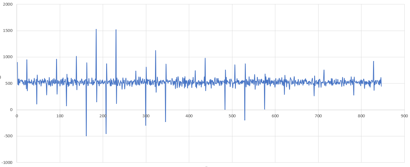
When using LES (WALE) i get a weird pressure drop between two cross-sections signal as shown in the pic below
June 2, 2021 at 10:38 amRob
Forum ModeratorIt may be linked to the LES-VOF interaction. Where is the monitor relative to the free surface?
June 3, 2021 at 6:24 ampeter_beshay
SubscriberHi Mr Rob for the LES-VOF interaction, i am running the same simulations but using ELES (2m pipe RANS + 0.5 m LES + 0.5 m RANS), and it runs fine, results are agreeing with experiments.
But when i run for just 1 m long LES in the whole domain, i get this strange pressure bursts. The monitor of the oil-water interface can be seen below, it looks reasonable.
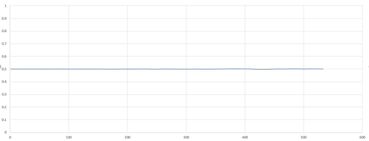 If changing the y-axis values, it will be still reasonable
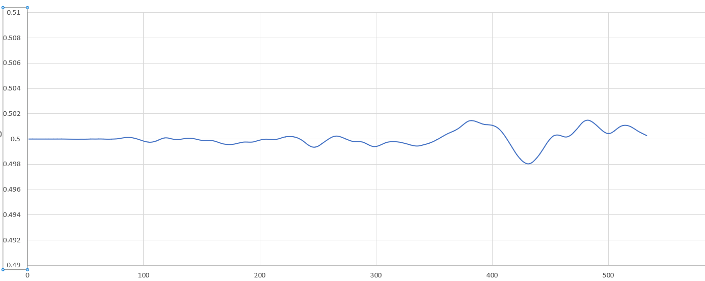 Do you have any idea why this pressure bursts would happen?
For the Laminar model or the K-omega using same geometry and mesh, pressure signal was very accurate
Thank you
June 3, 2021 at 1:50 pmJune 3, 2021 at 1:56 pmpeter_beshay
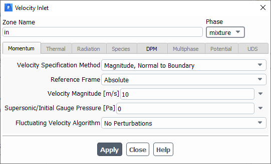
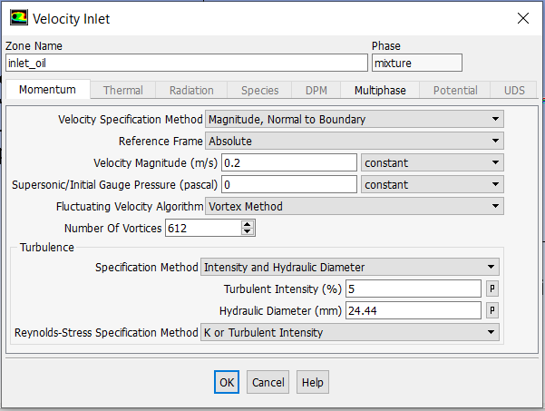
SubscriberHi Mr Rob The inlet of the pipe is split into upper and lower halves (the upper for oil, the lower for water). For both, i use the Vortex Method for Fluctuating velocity algorithm, and i put number of vortices as number of faces at the face divided by 4 (as suggested).
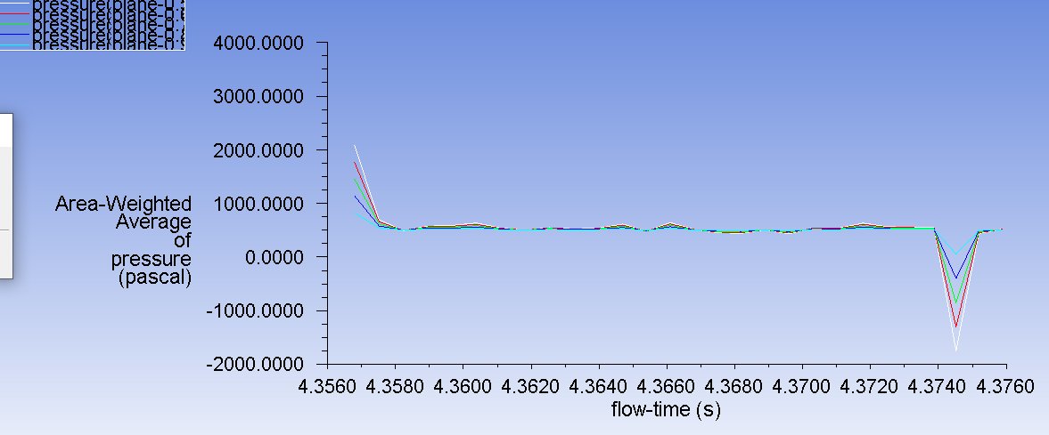
Actually, i was trying to run a case again, this time i switched transient formulation to 1st order implicit (instead of bounded 2nd order implicit), but still i get pressure bursts as seen in the below pic
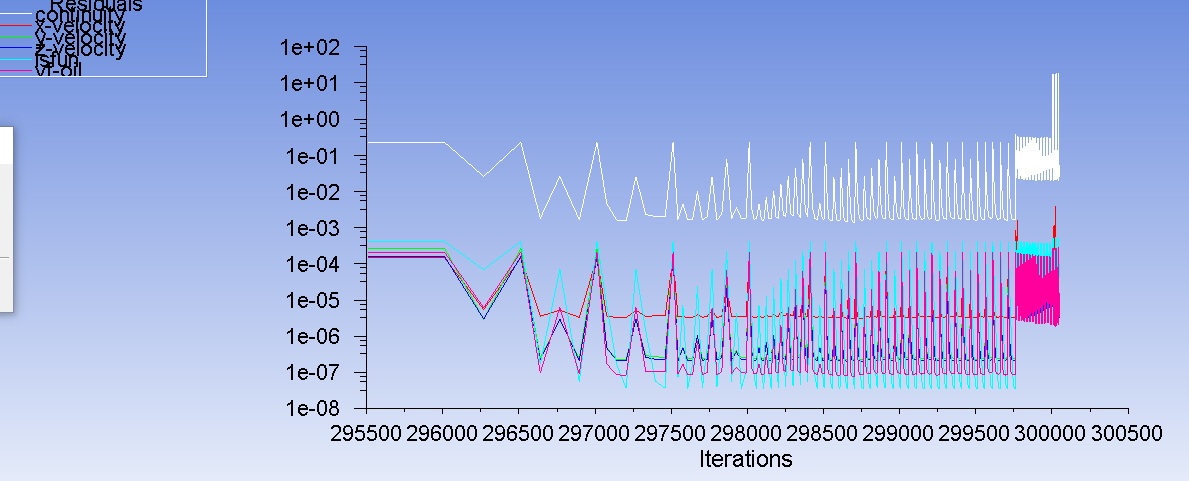
 The residuals are also seen below: (Before 30,000 iterations i was using K-Omega SST, then i switched to LES (WALE) as suggested)
June 3, 2021 at 2:40 pmRob
Forum ModeratorWhich will force the turbulence values near the free surface, whereas in reality turbulence is generally dissipated at the free surface as it's a break between the phases. I think the solver is doing what it's been told to, I think you need to separate the two fluids at the inlet to let the turbulent field stabilise.
June 3, 2021 at 3:01 pmpeter_beshay
SubscriberDear Mr Rob At the inlet, i have already separate inlets for each phase. I don't get what you mean by separate?
Also, when i run Embedded LES, results are perfect. But when i run LES for the whole domain, i get these pressure bursts.
How can i dissipate turbulence at the interface?
Thank you so much for your help.
June 3, 2021 at 3:04 pmRob
Forum ModeratorTry putting a slip wall into the model that extends about a diameter into the pipe, effectively a flat plate which separates the phases. In the other scenarios the flow has had time to sort itself out before the ELES section and k-w doesn't have a fluctuation as such other than the turbulence settings.
June 3, 2021 at 3:09 pmpeter_beshay
SubscriberDear Mr Rob I will try what you suggest, but that means changing the geometry and remeshing (you suggest adding like a baffle at the pipe inlet, right?
I am also trying to run now a case for just single phase water flow, to see the behavior of the pressure field with time.
Will update you when i get results.
Thank you so much for your help
June 3, 2021 at 3:31 pmRob
Forum ModeratorYes. If the mesh was extruded from the inlet you might beable to split a zone out and change the surface types. Otherwise see if you can extrude the mesh "upstream" to make the extra section.
June 5, 2021 at 2:03 ampeter_beshay
SubscriberJune 7, 2021 at 11:08 amRob
Forum ModeratorWith one or two inlet surfaces?
June 8, 2021 at 3:18 ampeter_beshay
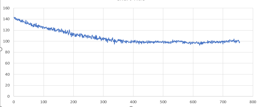
SubscriberHi Mr Rob I finally managed to get reasonable results, just wanted to update you with how i solved the problem, might be useful to others.
The curve below is the pressure difference between 2 cross sections in a horizontal pipeline, transporting oil and water in the stratified flow regime.
the circular inlet is split into two halves (upper for oil, lower for water).
i did not include any turbulence fluctuations at inlets (didnt use vortex method or spectral synthesizer), this solved the problem of bursting pressure values.
But could you explain to me why? In ansys documentation, it is recommended adding artificial turbulence at inlets when using LES.
Also when i use ELES, at the RANS/LES interface i add the vortex method and results are perfect.
Best regards Peter
June 8, 2021 at 6:53 amaitor.amatriain
SubscriberIf you have what ANSYS calls a "Globally Unstable Flow", then flow instability is enough to create turbulent structures, so the effect of velocity fluctuations at the inlet is negligible. The fact of having two separate inlet is definitely a source of instabilities, and I guess that that Re>>1.
If you have compared your LES results with experimental data, that's perfect. However, if there is no experimental data available, it is always interesting to include velocity fluctuations to see if there is any difference in the numerical results.
In any case, I am curious about why are you having problems with LES + velocity fluctuations.
June 8, 2021 at 6:57 ampeter_beshay
SubscriberHi Aitor i am simulating oil-water stratified wavy flow in horizontal pipeline (that's considered globally unstable?).
The effect of velocity fluctuations at inlets (using vortex method or spectral synthesizer) was not negligible, it leaded to pressure bursts (peaks) which where unphysical as you can see in the above figures.
The Re is not too high, around 5000-8000 for water and of the order of 200-300 for oil
I am also curious why problems appear when incorporating artificial turbulence at inlets for LES, while for embedded-LES, it works fine
June 8, 2021 at 7:04 amaitor.amatriain
SubscriberI would not say that your flow is globally unstable. Considering LES with no artificial turbulence generated at inlets, I would expect to obtain delayed turbulence structures. However, if you say that you are satisfied with the results given by this model, I imagine that it is more suitable than it seems.
In regards to your problem, you have said that your configuration is 2m pipe RANS + 0.5 m LES. What happens if you consider 1 m RANS sand 1.5 m LES? And if 0.5 m RANS and 2 m LES? Checking what happens when l_RANS ->0 can be interesting.
June 8, 2021 at 7:29 ampeter_beshay
SubscriberHi Aitor I cannot increase the LES region more than 0.5 meter because of the high mesh requirement for LES, for 0.5 meter i got over 2.7 million cells, i dont have computational resources to double or quadrable this number.
Viewing 16 reply threads- The topic ‘Large Eddy Simulation for oil-water stratified flow – Pressure signal problem’ is closed to new replies.
Innovation SpaceTrending discussionsTop Contributors-
4643
-
1540
-
1386
-
1225
-
1021
Top Rated Tags© 2025 Copyright ANSYS, Inc. All rights reserved.
Ansys does not support the usage of unauthorized Ansys software. Please visit www.ansys.com to obtain an official distribution.
-
The Ansys Learning Forum is a public forum. You are prohibited from providing (i) information that is confidential to You, your employer, or any third party, (ii) Personal Data or individually identifiable health information, (iii) any information that is U.S. Government Classified, Controlled Unclassified Information, International Traffic in Arms Regulators (ITAR) or Export Administration Regulators (EAR) controlled or otherwise have been determined by the United States Government or by a foreign government to require protection against unauthorized disclosure for reasons of national security, or (iv) topics or information restricted by the People's Republic of China data protection and privacy laws.


