Boris, what does the bushing joint in your model represent?
Suppose the bushing joint represents a nut and bolt that clamps two flanges together. The coefficients represent the stiffness of that bolted joint without modeling all the detail of the bolted joint.
One way to obtain the coefficients is to build a detailed model of the two flanges and the nut and bolt. Construct a small diameter of each flange around the hole, say a diameter 3 times the hole diameter. Hold the outer diameter of the bottom flange fixed. Add a Remote Point to the outer diameter of the top flange to track the displacements and rotations. Create Frictional contact between the flanges and use bolt pretension to clamp the flanges together in Step 1. In Steps 2, 3, and 4, apply a unit force (1 N) to the outer diameter of the top flange in the X, Y and Z directions, while in Steps 5, 6, 7, apply a unit moment (1 N-m) to the outer diameter of the top flange about X, Y and Z axes. Insert a Probe to get the directional deformation of the remote point in meters.
The bushing coefficient for X is 1/Xdef from Step 2. The bushing coefficient for Y is 1/Ydef from Step 3, etc. To be precise, you should subtract the Step 1 deformation from each of the subsequent steps to get the deformation from just applying the unit force or moment.
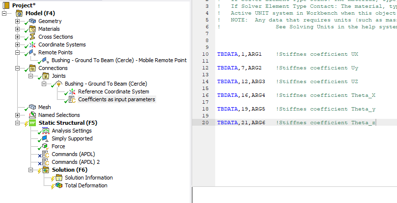
Make sure that the units on your model remain unchanged while you use it. For example if you solve the model in SI units, where the length unit is meters, keep that always set to meters. After you enter the coefficients, if you change units to mm for example, the stiffness will be off by a factor of 1000 when you solve in mm. You can be safe from that mistake if under Analysis Settings you force the solver to always solve in mks even if the units in Workbench are set to mm. This is the best practice.