TAGGED: fluent, heat-transfer
-
-
May 20, 2021 at 6:11 am
Danielgkh
SubscriberHi,
so I have a heat exchanger which consists of an hot fluid inner pipe and an cold fluid outer pipe. I have ran the simulation with two different setup, one with complete meshing of the whole heat exchanger and one with only the inner tube. Cold fluid is pumped into the heat exchanger at a high flow rate which keeps it at an almost constant temperature.
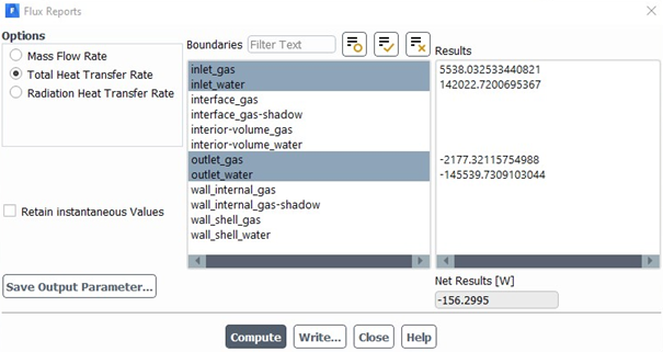
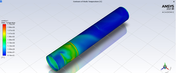
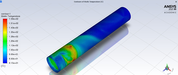
Whole heat exchanger
For this setup, I have set a coupled wall-wall shadow at the interface between the two fluid. There is no solid component in my simulation, only fluid.
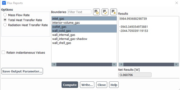
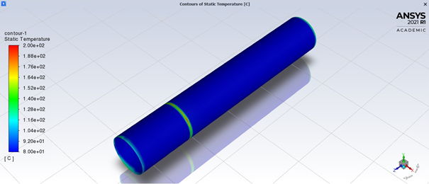
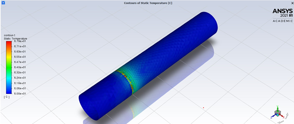
Only inner tube
For this setup, I have use a temperature wall boundary condition on the wall of inner tube, which I then set a wall temperature(same as cold fluid temperature)
Result
From the result, the outlet temperature from the 1st simulation is around 200C, from the 2nd simulation is around 300C. From the temperature contour, both of the simulation is conducting heat properly. So, any idea what might have caused this difference?
May 20, 2021 at 10:45 amRob
Forum ModeratorCheck the wall temperature on the cold side in the full model: chances are it's not quite the same as the fluid temperature.
May 20, 2021 at 3:39 pmDanielgkh
Subscriber
I have checked the wall temperature on the wall shadow facing the cold side of the full model. As expected, there are places where the temperature is higher than the cold fluid temperature as it is heated up by the hot fluid.
However the weird thing is, even though the full model has a higher wall temperature, it actually yields a lower outlet temperature than the partial model, which I don't understand.
May 21, 2021 at 10:21 amRob
Forum ModeratorLook at energy transfer too. I could have a small area at a high temperature or a larger area at a medium temperature which adds more energy (heat) to a flow. Re the flow temperature, are you looking at area or mass averages?
May 25, 2021 at 9:10 amDanielgkh
Subscriber
I have checked the flux reports for both of the model, they seem fine enough to me.
Full model flux report
Partial model flux report
As for the temperature, I directly plot a temperature contour on the wall in interest.
Full model temperature contour
Partial model temperature contour
As you can see, the full model has a higher wall temperature which should result in a higher exhaust gas temperature. However thats not the case here.
Both of the model uses realizable k-e model with enhanced wall treatment. Both uses self-defined air as material as there is a big change in temperature.( 450 C ~ 200C)
Thanks in advance.
May 25, 2021 at 9:59 amRob
Forum ModeratorYou're transferring around 2,200W in the first case and 2,000W in the second with a good energy balance assuming no losses to "outside" in the first case.
Re plot the images with node values off: you're seeing the interpolated value on the wall which is influenced by the wall facet (latter case) and other fluid domain (first case).
May 25, 2021 at 11:46 amDanielgkh
Subscriber
I do understand that from the simulation result, there is more heat transferred out in my full model than partial model which cause the exhaust gas temperature to be lower. However, from my understanding, since the wall of partial model is kept at a constant cold temperature, shouldnt it be able to "extract" more heat from the hot gas, thus lowering the exhaust gas temperature more? By the way, I had specified the wall thickness in both cases.
Here are the re plot of the images.
Temperature contour full model
Temperature contour partial model
There is a round plate in the middle of the component which caused the strip of high temperature, not to be suprised by that.
May 31, 2021 at 5:21 amDanielgkh
SubscriberSo, is there any explanation to this situation?
June 1, 2021 at 11:51 amRob
Forum ModeratorWhat is the mass weighted outlet temperature in both cases?
June 2, 2021 at 5:47 amDanielgkh
SubscriberHi thanks so much for your reply.
The mass weighted and area weighted outlet temperature for the full model is 197 C.
The mass weighted and area weighted outlet temperature for the partial model is 327 C.
Both of the model has a fixed inlet temperature of 450 C.
June 2, 2021 at 8:23 amRob
Forum ModeratorWith the same mass flow and fairly similar heat flux? Can you carefully go though the results, ie contours of temperature & velocity are probably best to see what's going on in the domain?
To confirm, area and mass average is the same (or near enough)?
Viewing 10 reply threads- The topic ‘Difference between temperature wall boundary condition and actual meshing of heat exchanger’ is closed to new replies.
Ansys Innovation SpaceTrending discussions- air flow in and out of computer case
- Varying Bond model parameters to mimic soil particle cohesion/stiction
- Eroded Mass due to Erosion of Soil Particles by Fluids
- I am doing a corona simulation. But particles are not spreading.
- Centrifugal Fan Analysis for Determination of Characteristic Curve
- Guidance needed for Conjugate Heat Transfer Analysis for a 3s3p Li-ion Battery
- Issue to compile a UDF in ANSYS Fluent
- JACOBI Convergence Issue in ANSYS AQWA
- affinity not set
- Resuming SAG Mill Simulation with New Particle Batch in Rocky
Top Contributors-
3977
-
1461
-
1272
-
1124
-
1021
Top Rated Tags© 2025 Copyright ANSYS, Inc. All rights reserved.
Ansys does not support the usage of unauthorized Ansys software. Please visit www.ansys.com to obtain an official distribution.
-