

-
-
May 17, 2021 at 3:26 pm
mdhiz97
SubscriberMay 19, 2021 at 12:08 pm1shan
Ansys EmployeeCould you please insert inline images while posting since ANSYS staff are not allowed to download attachments. You could have a look at https://www.youtube.com/watch?v=svE0ZW6QrrY and try something similar. If you don't want to model the actual bar by defining contacts, you could simply use a remote force and remote displacements instead. You will have to split the main bar into 4 sections in space-claim to apply remote force in the middle and displacements at the ends. You may also want to make use of symmetry and model just half of the bar. Additionally use a kinematic hardening model to simulate cyclic loading. This is another useful discussion - /forum/discussion/2667/three-point-bending.
Regards Ishan.
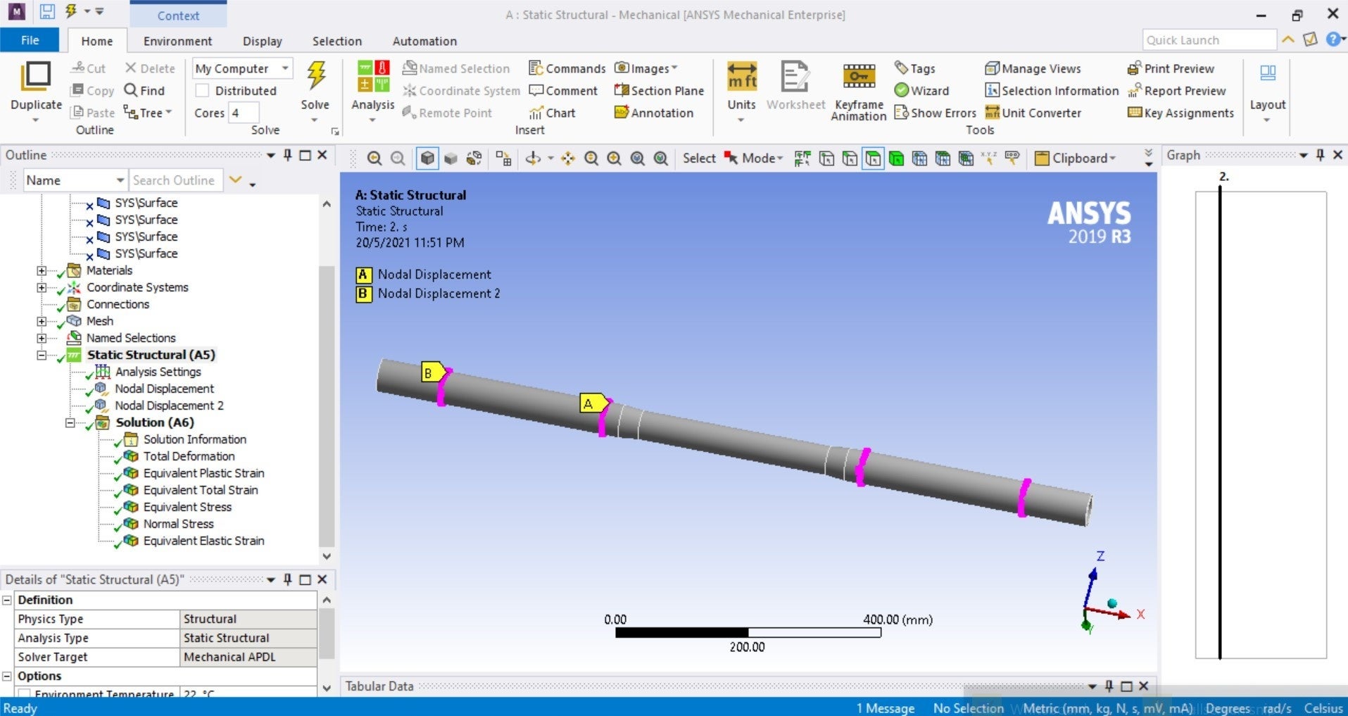
May 20, 2021 at 3:59 pmSubscriberThank you very much for the prompt response. As requested, I have attached inline images for your review.
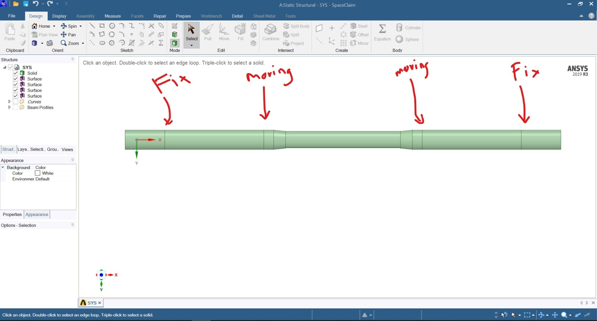
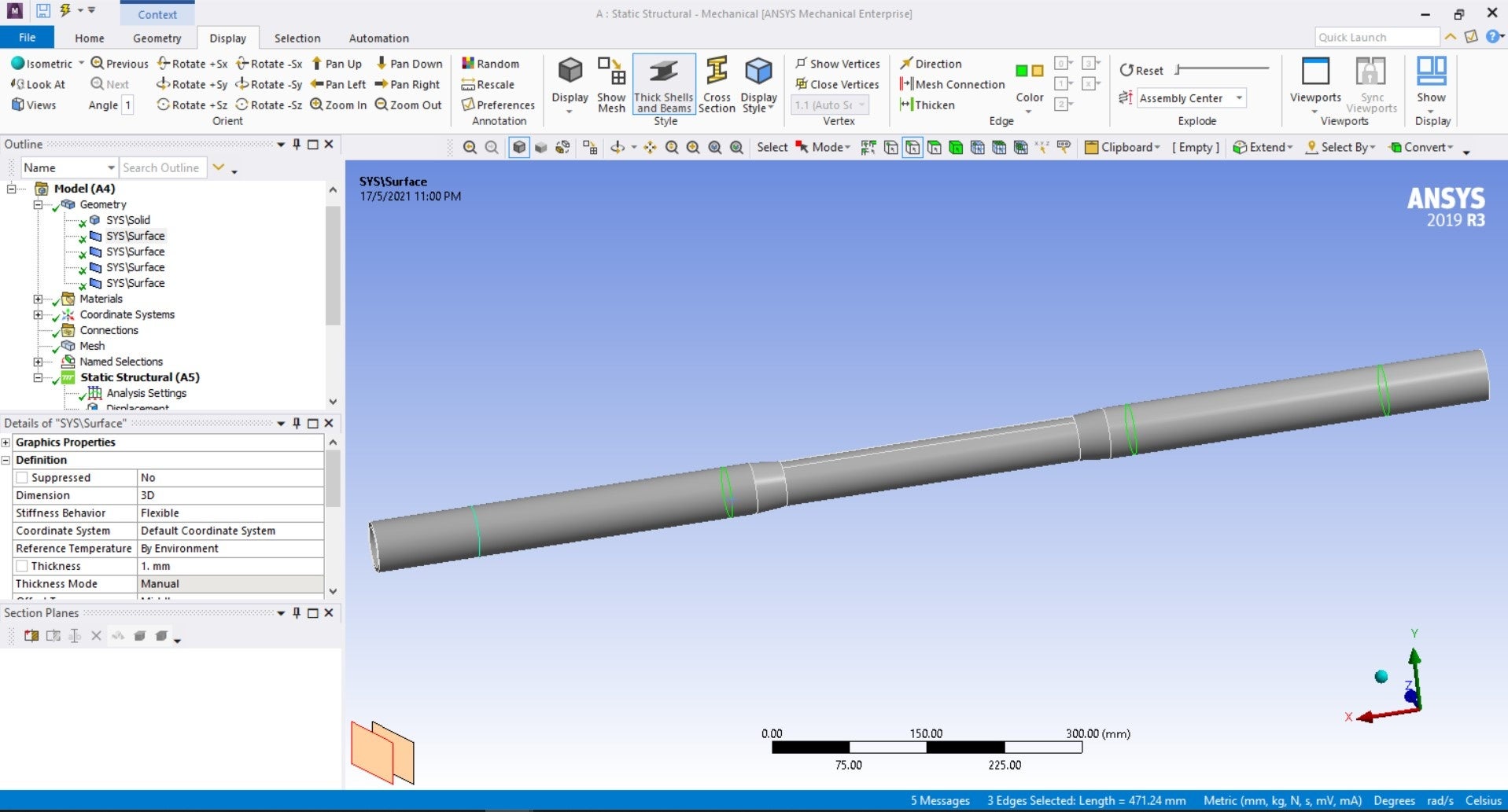
 I have tried another method where I apply the load using nodal displacement. I highlighted the nodes around the applied loading in order to stimulate the experimental setup as shown in the figure below.
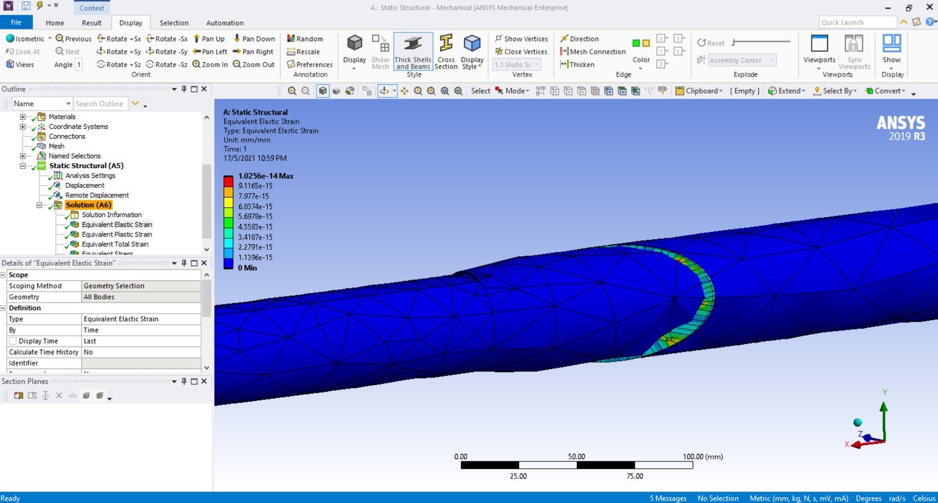
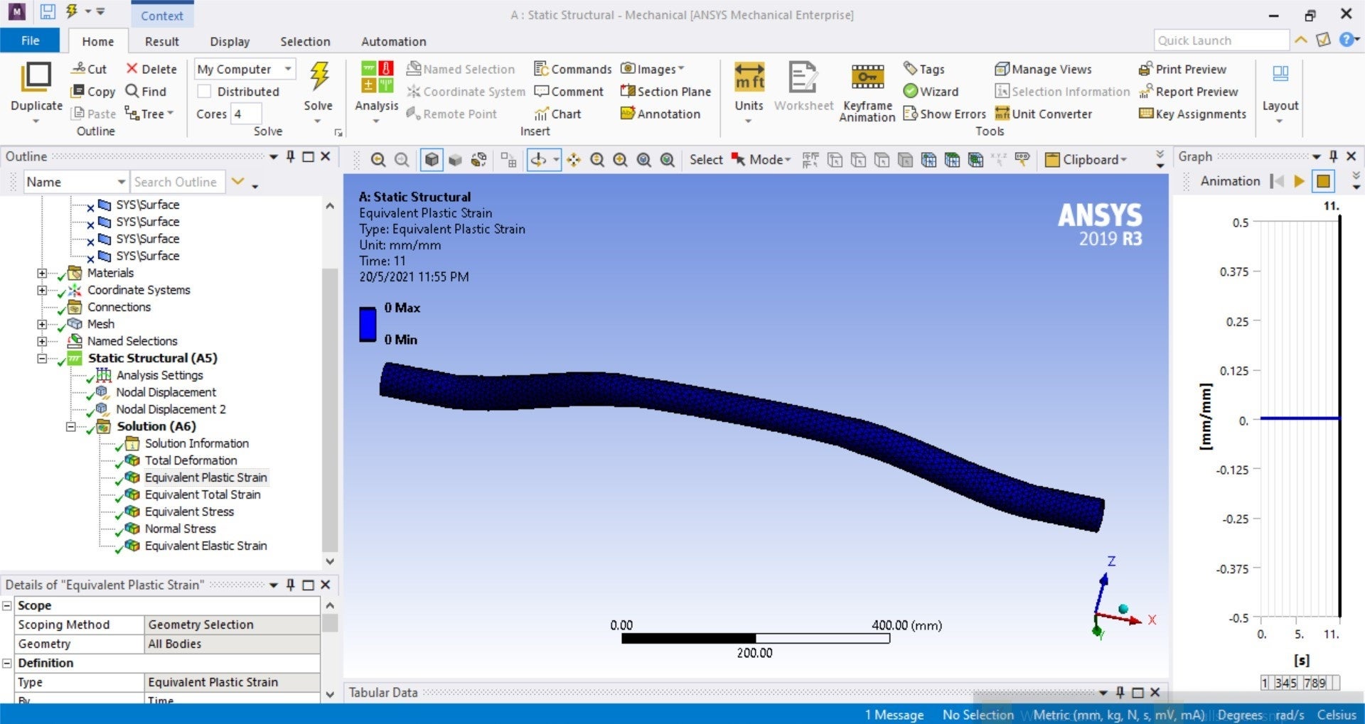
 So far it runs well however, I still could able to get the result for Equivalent Plastic Strain as can be seen in the figure below. I could not get the plastic strains, there aren't any plots too. I have included Chaboche kinematic hardening and Multilinear isotropic hardening. Still, I could not get the results.
Looking forward to your guidance and advice. Thank you.
May 20, 2021 at 3:59 pmSubscriber
May 21, 2021 at 3:37 amAnsys EmployeeWhat is the yield stress value defined in engineering data? Could you check the equivalent stress result and see if stress in any region exceeds this value? Also, instead of fixing the ends scope a remote displacement to the circular edges (surface splits), free translation rotation in Z and fix rest. The mesh quality can also be improved to an all quad mesh. And I hope you have set Large deflection under analysis settings to "on".
Regards Ishan.
July 7, 2021 at 11:15 pmSubscriberDear , thank you. I was able to stimulate the four-point bending test. I did have a mesh problem as stated in my other post:- Transparent face after meshing multizone ÔÇö Ansys Learning Forum.
Viewing 5 reply threads- The topic ‘Stimulate Four Point bending Test ( hysteresis loop)’ is closed to new replies.
Ansys Innovation Space Trending discussions
 Top Contributors
-
peteroznewman
 3582
3582 -
scabo
 1193
1193 -
Dennis Chen
 1086
1086 -
javat33489
 1063
1063 -
Shyam Prasad V Atri
952
Top Rated Tags
© 2025 Copyright ANSYS, Inc. All rights reserved.
Ansys does not support the usage of unauthorized Ansys software. Please visit www.ansys.com to obtain an official distribution.
-


The Ansys Learning Forum is a public forum. You are prohibited from providing (i) information that is confidential to You, your employer, or any third party, (ii) Personal Data or individually identifiable health information, (iii) any information that is U.S. Government Classified, Controlled Unclassified Information, International Traffic in Arms Regulators (ITAR) or Export Administration Regulators (EAR) controlled or otherwise have been determined by the United States Government or by a foreign government to require protection against unauthorized disclosure for reasons of national security, or (iv) topics or information restricted by the People's Republic of China data protection and privacy laws.


