

TAGGED: fdtd, phase-change, waveguides
-
-
May 7, 2021 at 2:19 am
e0452768
SubscriberHi everyone,
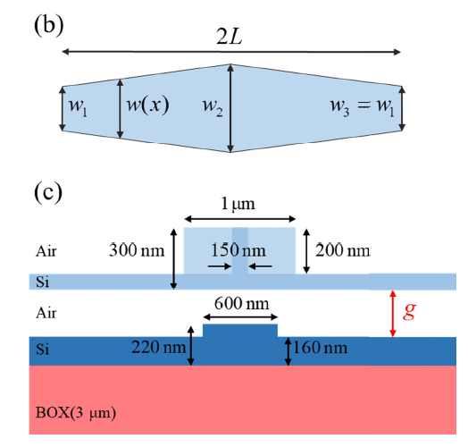
I am trying to reproduce the paper https://doi.org/10.1364/OE.27.018959, which is going to change the vertical gap between two vertical directional couplers to get phase change. Figures attached below are the schematic presentation of the phase shifter system, the FDTD::port location, and relative phase change versus the vertical gap, respectively.
May 7, 2021 at 2:21 amSubscriberI am sorry that I forgot to attach my own simulation files.
May 10, 2021 at 10:58 amGreg Baethge
Ansys EmployeeThank you for posting your question. I'm not allowed to download your files (see this post), so I will and provide some answers based on the information you shared. First, since you are using ports in your simulation, you can get the phase information from the S parameter in Port 2 (corresponding to S21).
Also, the structure is quite long, over 60um. With such dimension, you have to make sure the simulation time is long enough for the source pulse to travel all the way through the structure, and be absorbed by the PMLs. You can check this by monitoring the auto shutoff level of the simulation (from the simulation log file, for example). This represents the fraction of energy left in the simulation volume. We want the auto shutoff level to be below 1e-5 by the end of the simulation. If it didn't reach this threshold, you need to increase the simulation time (default value is 1000fs).
As FDTD is a time domain method, we get the frequency domain fields from the time domain ones using a Fourier transform. If the fields have not decayed enough by the end of the simulation, the Fourier transform will show some artifacts that will affect the result accuracy. The auto shutoff level is used for that purpose. When it reaches the threshold, we stop the simulation.
I hope this will help.
May 10, 2021 at 1:24 pmSubscriber
Thanks for your detailed reply very much!
I did the simulation again and extract phase information from the S parameter in Port 2. The script is shown below:
port1S = getresult('FDTD::ports::port 1','S');
port2S = getresult('FDTD::ports::port 2','S');
freq = port1S.f;
S21_phs_n1 = unwrap(angle(port1S.S))*180/pi;
S21_phs_n2 = unwrap(angle(port2S.S))*180/pi;
plot(freq*1.0e-12,S21_phs_n1,S21_phs_n2);
legend('port 1 phase','port 2 phase');
Other simulation setup are shown below:
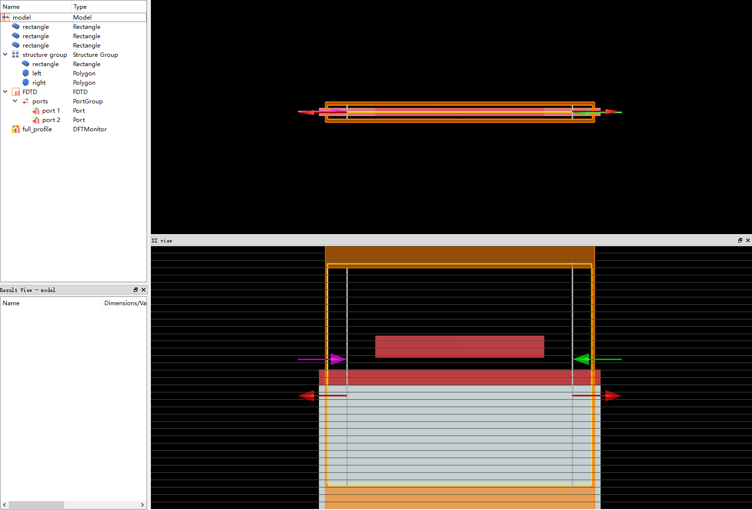
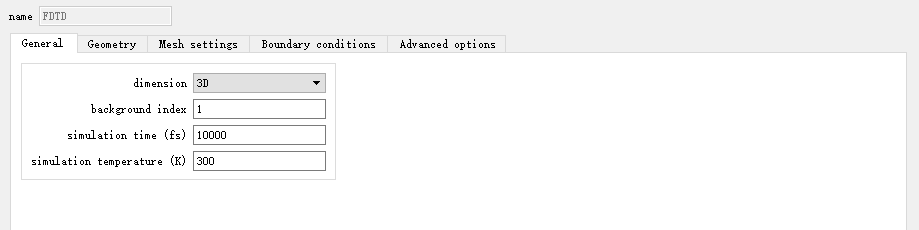
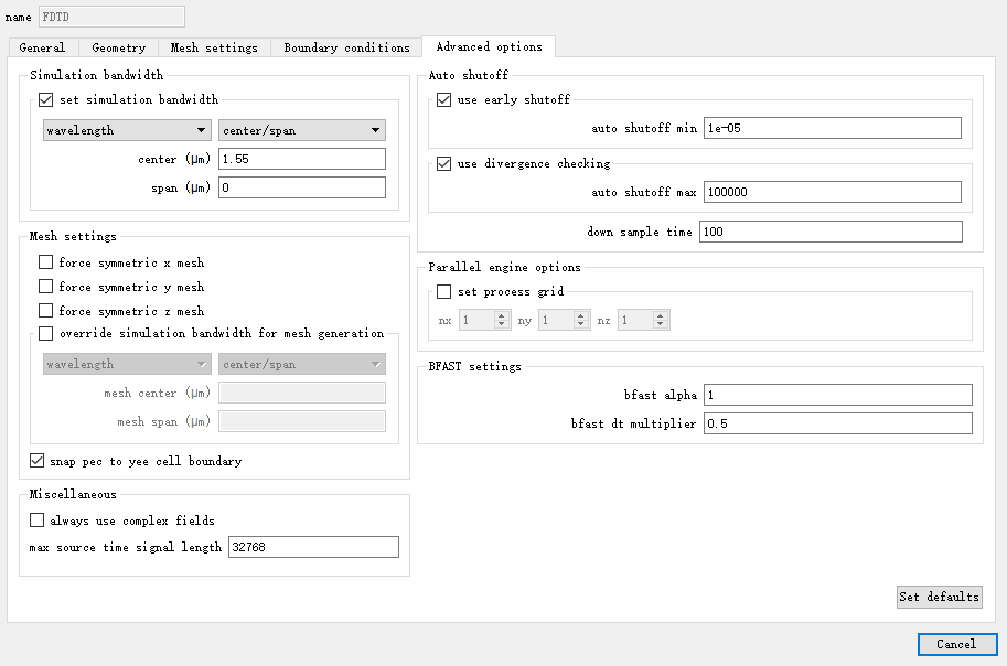
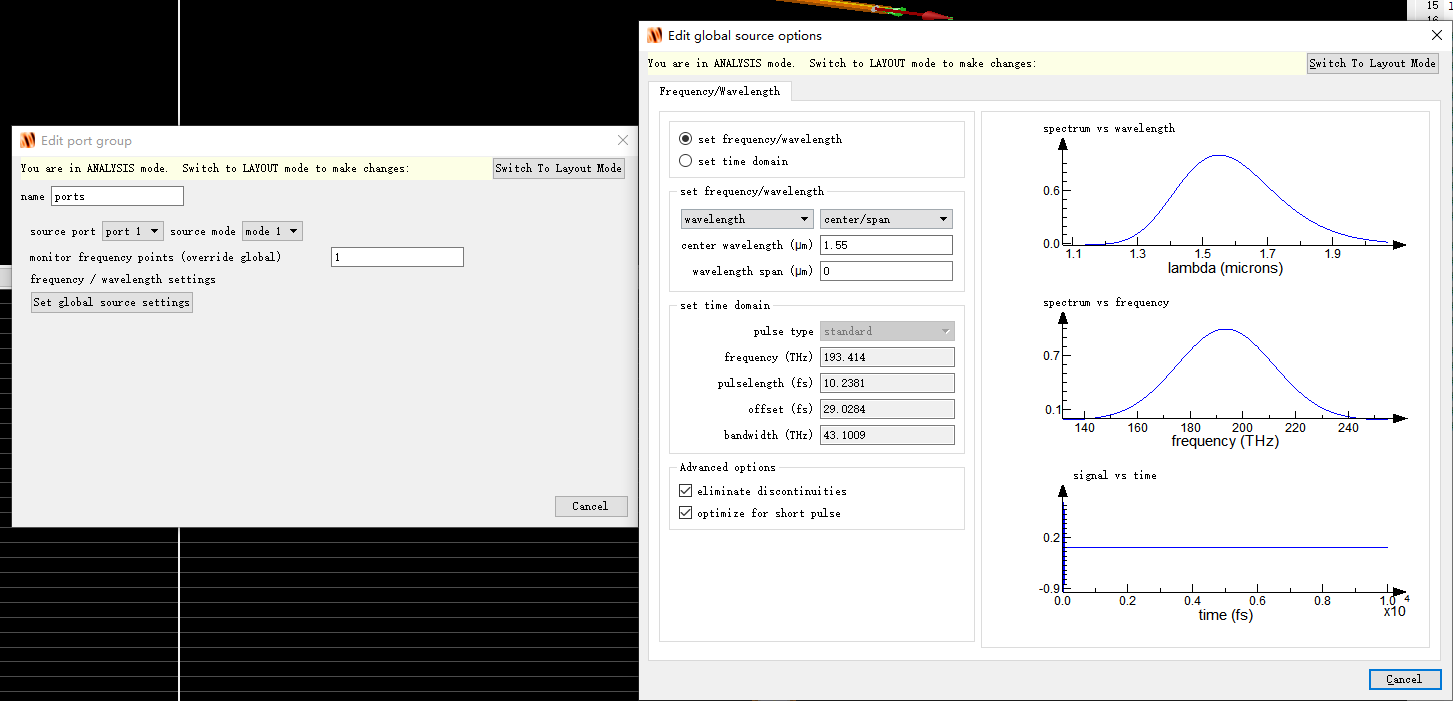
Then the simulation results obtained from running the script are shown below.
 First of all, I am sorry that posting so many pictures. I still have several problems.
The script I used was copied from someone who has a similar problem. However, I am not sure whether I extract phase(S21) correctly or not.
I am not sure what's the meaning of angle(port2S.S), does it mean the relative phase change between port 1(input mode) and port 2(output mode), or does it mean the absolute phase value of output mode at port 2?
What's the meaning of unwrap(angle(port1S.S))*180/pi? Does it mean the phase information of S12? Or does it mean the absolute phase value of input mode at port 1?
According to the results, I found that the phase values at port 1 with different gap values are different. I do not know how to explain this phenomenon. Because I assume that the phase value I extracted at port 1 is the absolute phase information of the input TE0 mode. In this case, does it mean in every simulation, the initial phase value of input TE0 mode is random?
I am sorry for asking about so many problems at one time. Because I cannot find much more information about extracting phase information from the waveguide using FDTD::port.
I would appreciate it if you can check it out, and if you feel confused about any part of my description, please feel free to let me know.
Many thanks,
Haoyang
May 10, 2021 at 3:43 pmAnsys EmployeeHi Haoyang You're very welcome. Thanks for the additional information. Posting many pictures is not an issue, quite the contrary, it is very helpful to understand the simulation settings and what you are trying to do.
First, regarding the meaning of the S parameters:
port1S = getresult('FDTD::ports::port 1','S');
port2S = getresult('FDTD::ports::port 2','S');
In the simulation, port 1 is used as a source, so port1S represent S11, the fields reflected by the device, and port2S represents S21, the fields transmitted by the device. With that in mind, it is normal both are affected when you change the gap. In your case, I think you only need to get S21. The phase of S21 will give you what you need, the phase difference with respect to the fields injected in the source (port 1).
S21_phs_n1 = unwrap(angle(port1S.S))*180/pi;
S21_phs_n2 = unwrap(angle(port2S.S))*180/pi;
The angle() command will give the phase of a complex number in radians. We use unwrap() to remove the changes of more than 2pi, for example:
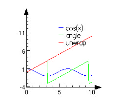 unwrap simply allows to get a continuous plot of the phase.
Let me know if you have any further question.
May 13, 2021 at 4:39 amSubscriber
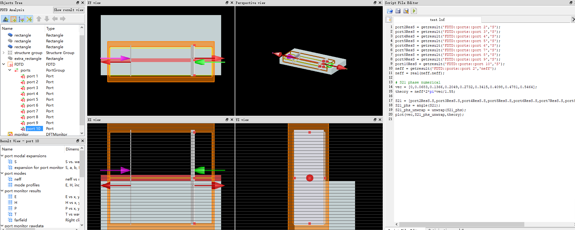 To verify my phase measurement setup, I built a test model which consists of a straight waveguide, one input port, and nine output ports. Input is TE0 mode whose wavelength is 1.55 ╬╝m. Port 1 is set as forward and port 2 to 8 are all set as backward. Vector 'vec' is the relative location of ports 2 to 8 compared with port 2. Then I extract phase information from port 2 to 8 and compared with theoretical phase change. The result is shown below. The X-axis is the relative location of each port and the y-axis is the unwrap phase value.
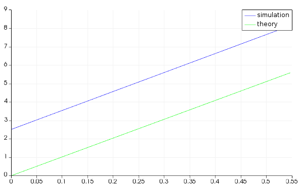 According to the picture, I find that simulation and theory match well, even though there is a constant offset. So I am convinced that the setup is correct.
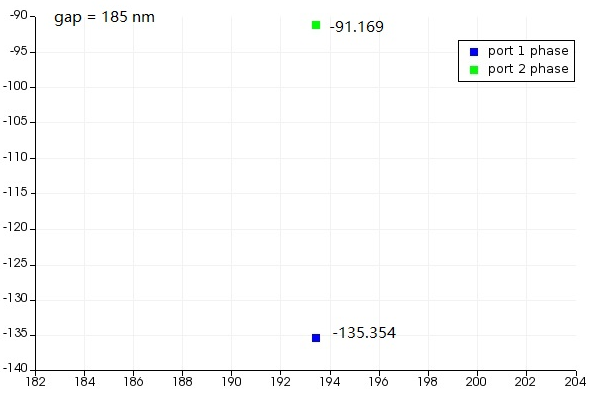
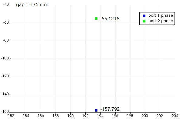
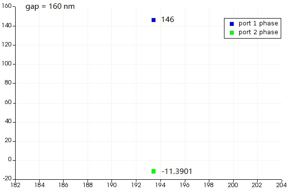
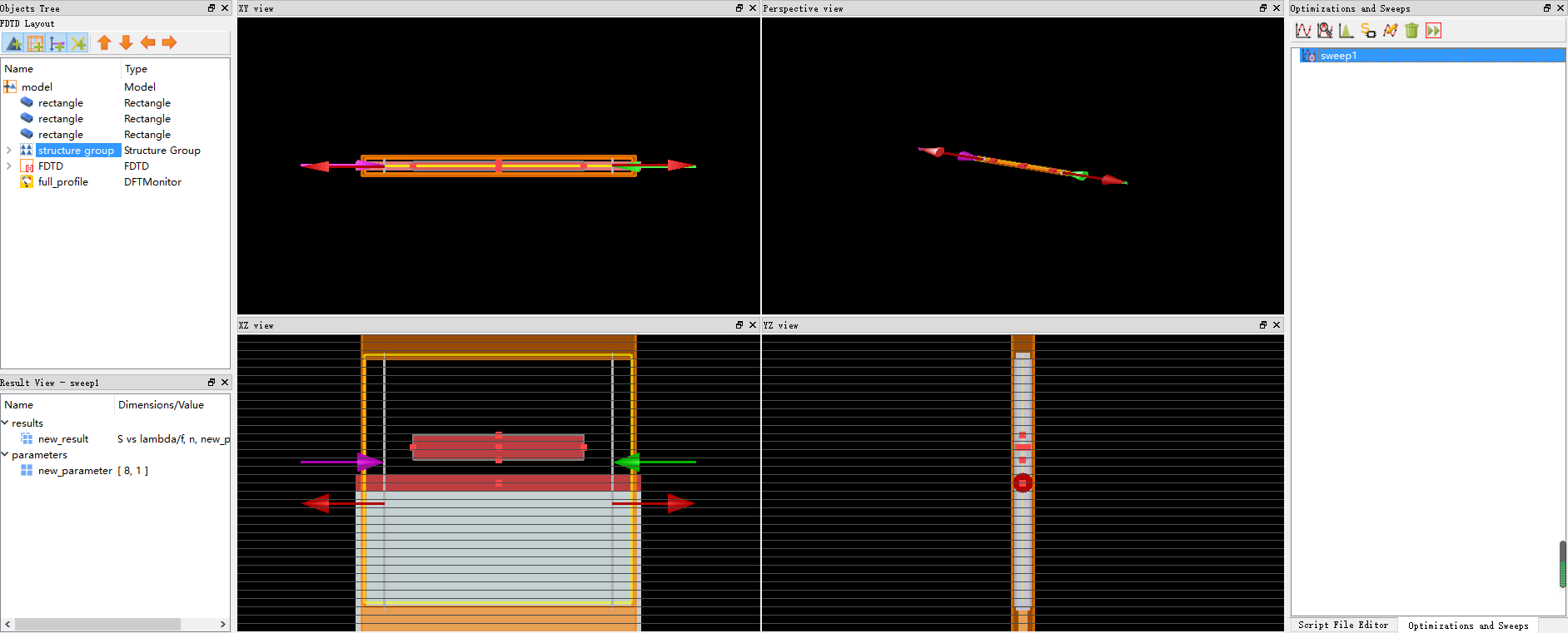
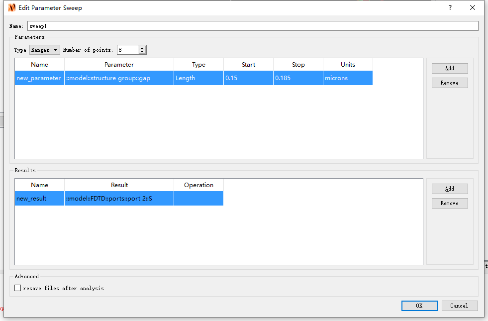
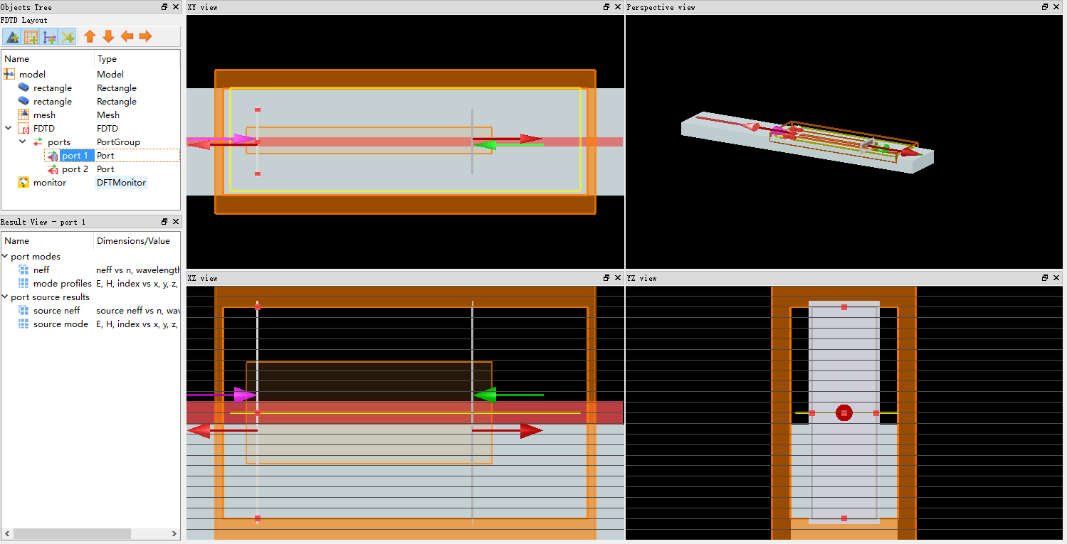
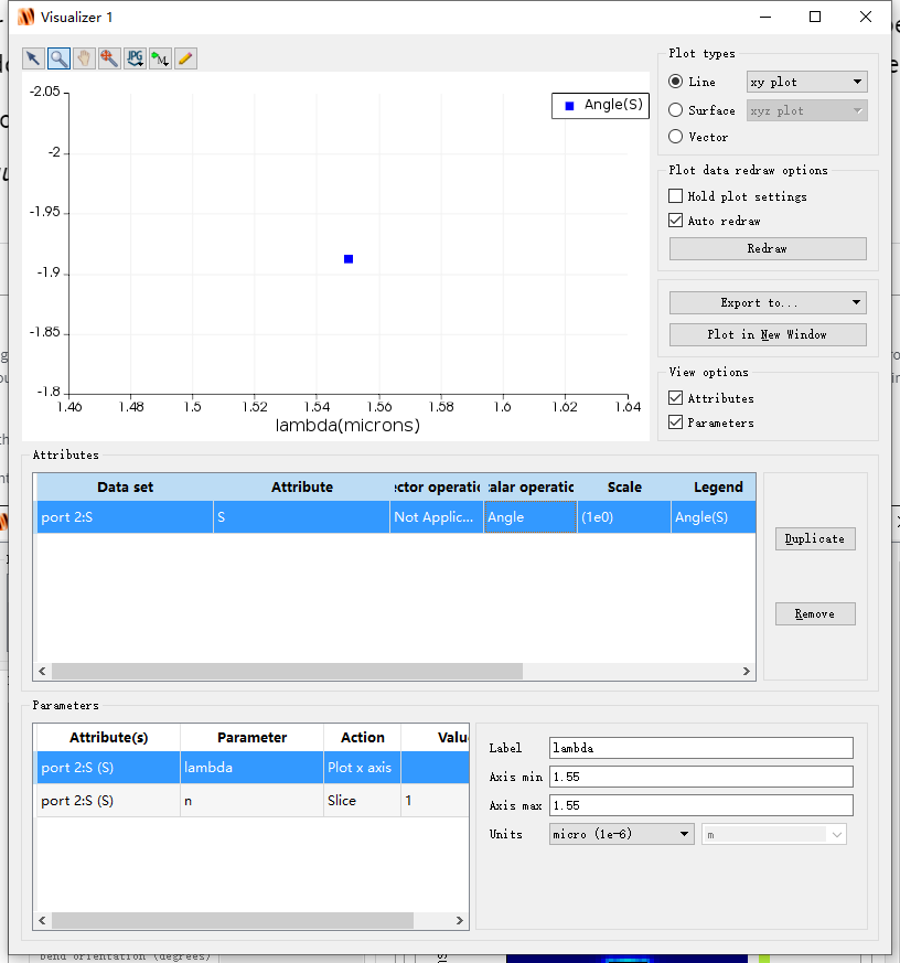
Next, I reproduce the verticle directional coupler phase shifter. At this time, I sweep the gap and extract phase information. The sweep setup is shown below. ''::model::structure group::gap" is the vertical gap of the verticle directional coupler. "::model::FDTD::ports::port 2::S" is S21.
 The sweep results are shown below.
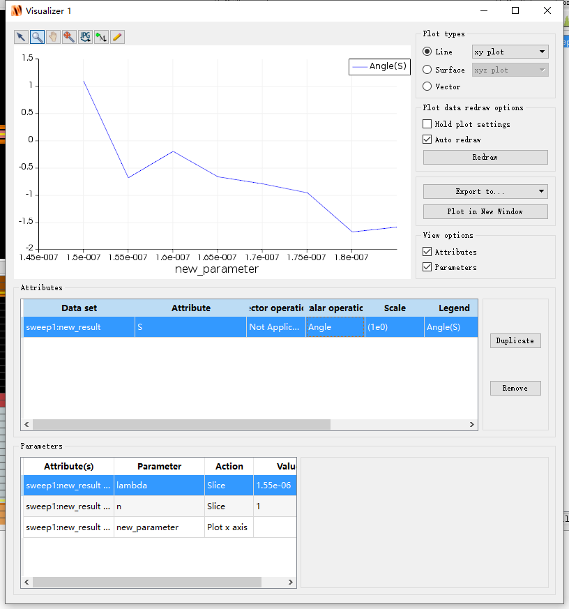 The phase curve is weird and the relative phase change is around pi which is no agreement with the paper whose phase change is 2pi. So I am confused and do not know where is my problem. Could you please check and find where is my problem?
Many thanks Haoyang
May 13, 2021 at 9:10 amAnsys EmployeeHi Haoyang First, I think the shift you observe between the phase from the S parameter and the theoretical one is just because you calculated the phase difference from port 2, while S will give the phase with respect to port 1. So the shift is just due to the additional phase between port 1 and port 2.
Regarding the sweep result, the first thing I would check is the mesh: the coupling between the 2 waveguide is obviously very dependent on the gap. Although the conformal mesh improves the accuracy, you may want to check there's a few mesh cells between the 2 waveguides. Additionally, you can use a mesh override object to force an integer number of mesh cells in the gap so the silicon/air interfaces are on a mesh cell and not in the middle.
You can also check the ports and simulation size: ports should be large enough so the mode fields are weak at the boundaries. Typically, we want the fields to be a few order of magnitude smaller than their peak value. If not, some diffraction may occur from the fields being truncated. For the simulation region, you want the PML to be far enough from the waveguides so they don't affect the fields. Make also sure the substrate and Si slabs extend through the PML.
Finally, you can run some convergence testing to check the simulation settings.
May 24, 2021 at 4:41 pmSubscriber
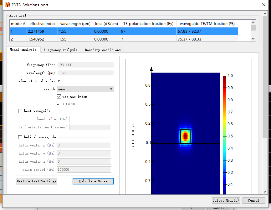
I am still confused about extracting phase information using FDTD::port. I have tested this method with the simplest model that TE0 mode whose wavelength is 1.55 ╬╝m travels through one strip waveguide. The distance between input port and output port is 10 ╬╝m, and neff = 2.27146. In this case, phase change = neff*2*pai*10/1.55 = 92.077. However, I extracted phase information using command unwrap(angle(S21))*180/pi and the result is -109.562.
The input port is set forward and the output port is set backward. The simulation is autoshutoff. Override mesh size is set 0.03 ╬╝m for x,y and z directions.
There may be something important that I missed. Besides, are there any other methods to extract phase information from waveguide?
Many thanks Haoyang
May 25, 2021 at 1:05 pmAnsys Employee
Thanks for the update. I don't think you need any conversion: both phases (either taken using "angle" or calculated directly from the effective index and the propagation length) are in radians. Also, we have to keep in mind phase and phase + n*2*pi represent the same phase difference.
Another important point is, the phase is quite sensitive to the mesh size. Because of the grid dispersion, the error in the phase will accumulate through propagation.
As a test, I used a similar setup as yours, although the distance between the ports is 5um in my simulation. I calculated the phase shift from the effective index and from angle(S), and I calculated the modulus of the phase shift after dividing by 2*pi and compared it to angle(S) + 2*pi, for different mesh sizes (over the waveguide).
dx=dy=25nm - dz=20nm
dphi=48.21587691705104
from S:-1.982228848025093
mod(dphi, 2*pi) = 4.233579766793937
angle S + 2*pi = 4.300956459154493
dx=dy=dz=10nm
dphi=48.19349786662514
from S:-2.055191586415779
result:
4.211200716368040
result:
4.227993720763807
dphi varies with the mesh size as it affects the effective index calculation, but it affects angle(S) much more (due to the grid dispersion). With 10nm mesh size on the waveguide, and a mesh accuracy of 2, the error on the phase is about 0.4%, which is reasonable. Some convergence testing could probably improve this.
I hope this will help!
Viewing 8 reply threads- The topic ‘Extracting TE mode phase information using FDTD::port on the waveguide’ is closed to new replies.
Innovation Space Trending discussions
 Top Contributors
-
peteroznewman
 6450
6450 -
scabo
 1906
1906 -
Dennis Chen
 1457
1457 -
javat33489
 1308
1308 -
Shyam Prasad V Atri
1022
Top Rated Tags
© 2026 Copyright ANSYS, Inc. All rights reserved.
Ansys does not support the usage of unauthorized Ansys software. Please visit www.ansys.com to obtain an official distribution.
-


The Ansys Learning Forum is a public forum. You are prohibited from providing (i) information that is confidential to You, your employer, or any third party, (ii) Personal Data or individually identifiable health information, (iii) any information that is U.S. Government Classified, Controlled Unclassified Information, International Traffic in Arms Regulators (ITAR) or Export Administration Regulators (EAR) controlled or otherwise have been determined by the United States Government or by a foreign government to require protection against unauthorized disclosure for reasons of national security, or (iv) topics or information restricted by the People's Republic of China data protection and privacy laws.
