

-
-
May 6, 2021 at 4:35 pm
xh19363
SubscriberI would like to find the directivity pattern of a grating antenna. I have found the far field in 2D and 3D using the scrips farfield2d and farfield3D. But, I would like to apply the "directivity" analysis group in the antenna and find the directivity pattern. I have read the example with the Rectangular Probe Antenna and far field directivity calculations of an antenna and I would like to do the same with my antenna.
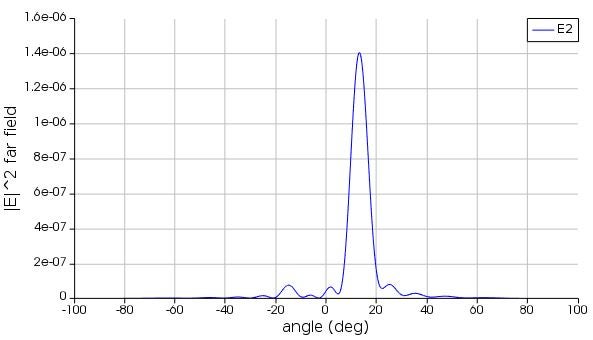
Here I present you the farfield2D
May 6, 2021 at 9:27 pmTaylor Robertson
Ansys EmployeeHello First you will need to ensure the set -up of the directivity monitor is correct. Are the cladding and substrate both isotropic silica so that you are in a single homogenous medium? You may find the box monitor easier to use Far-field-projections-from-a-box-of-monitors. If this is the case then the resulting directivity will be into silica not air, so be careful. The directivity analysis here is used to create an opening for the antenna feed, so that you can work within this homogenous media constraint, and it returns values more commonly used in RF then optical. That being said it should work and return the quantities you are interested in.
I can see that the theta value range is, from 0 to ¤Ç. I was expecting to plot the directivity which should have a specific theta. If I am not mistaken, the antenna can't have many directivity patterns for different theta values, only just one pattern. The theta value is supposed to be just one value for a specific antenna.
This not true if you refer to the wikipedia reference or an Antenna Engineering textbook you will see that Directivity D(theta,phi) is a 3D pattern. This misconception may come from the fact in RF a 2D plot of the plane normal to the dipole axis is usually given, since this will always be the plane where you see the max directivity. A dielectric grating antenna, however, will couple to oblique angle radiation and this is wavelength dependent. To build more intuition you may want to look at the 3D directivity plots given in the LIDAR antenna example.
https://support.lumerical.com/hc/en-us/articles/360042305234-Light-detection-and-ranging-LiDAR-antenna
For more information on the spherical coordinate system see this page https://support.lumerical.com/hc/en-us/articles/360034394294-FFP-Direction-unit-vector-coordinates. Also as you noted the set-up variables allow you to changer the resolution of theta and phi.
If you look at the analysis script you should see how D the maxium value of that directivity is found. I hope this helps.
Best
Viewing 1 reply thread- The topic ‘Directivity of a grating antenna’ is closed to new replies.
Innovation Space Trending discussions
 Top Contributors
-
peteroznewman
 6455
6455 -
scabo
 1906
1906 -
Dennis Chen
 1457
1457 -
javat33489
 1308
1308 -
Shyam Prasad V Atri
1022
Top Rated Tags
© 2026 Copyright ANSYS, Inc. All rights reserved.
Ansys does not support the usage of unauthorized Ansys software. Please visit www.ansys.com to obtain an official distribution.
-


The Ansys Learning Forum is a public forum. You are prohibited from providing (i) information that is confidential to You, your employer, or any third party, (ii) Personal Data or individually identifiable health information, (iii) any information that is U.S. Government Classified, Controlled Unclassified Information, International Traffic in Arms Regulators (ITAR) or Export Administration Regulators (EAR) controlled or otherwise have been determined by the United States Government or by a foreign government to require protection against unauthorized disclosure for reasons of national security, or (iv) topics or information restricted by the People's Republic of China data protection and privacy laws.
