-
-
May 2, 2021 at 9:49 am
isit12
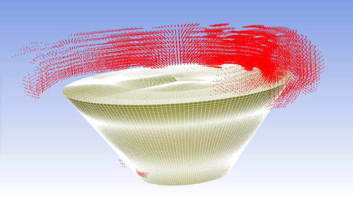
SubscriberI am trying to calculate coefficient of performance for a vertical axis wind turbine. The turbine blade is 90 meter long. While running simulation in fluent, initial residuals are converging well. After a while, the warning appears saying 'turbulent viscosity limited to viscosity ratio of 1.000000e+05 in XXX cells'. I checked the areas where the turbulent viscosity ratios are very high. Initially it is around the interface area where I am using sliding mesh interface. Then the number of cells keeps on increasing, mostly outside of inner rotating domain. I found on the internet that it could be because the turbulent eddies are not being properly resolved as a result of large mesh size or non-uniformity of mesh. I checked the non-uniformity of mesh around the interface and refined it. The problem was still there. I also tried reducing the time step, increasing or decreasing relaxation parameters, altering turbulence model but couldn't get out of the problem. I am getting the results from the simulation, but I am sure the results are non-physical. What could be the issue causing high turbulent viscosity ratio. Is it because of two interfaces having different distribution of mesh or the shape of interface?
May 2, 2021 at 2:12 pmRob
Forum ModeratorThe limiter can be adjusted, Solve - Controls from memory. For large domains it's common to add a few 0's to the limiter! Have a look at the velocity gradients in that area: are they well resolved?
May 2, 2021 at 5:13 pmSubscriber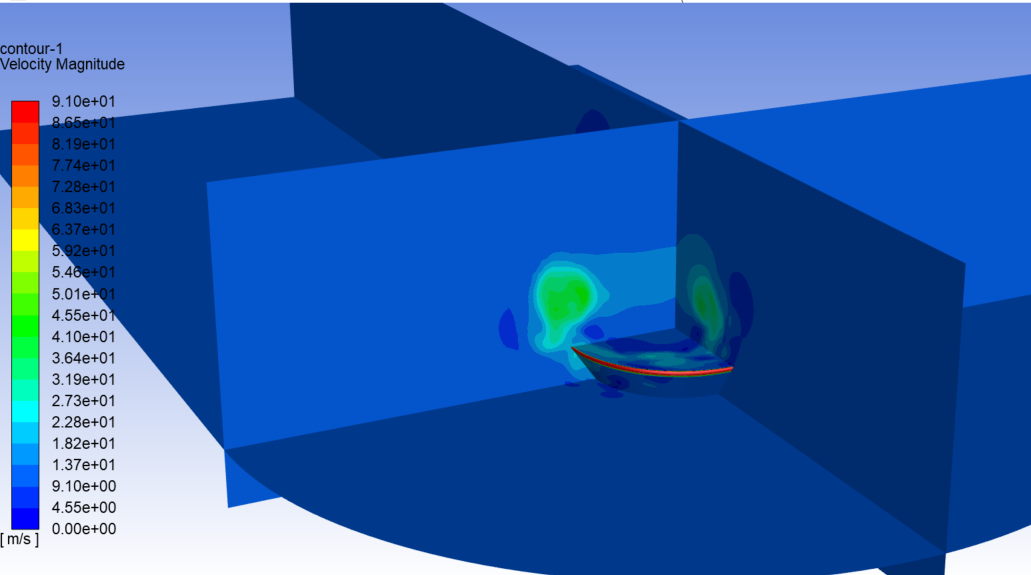
 Hi Rob,
Thank you for answering my queries.
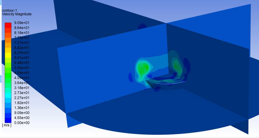
The first two figures are velocity contours in a quadrant formed by X=0,Y=0 and Z=50 m planes and inner rotating domain. First figure has rotating domain inner interface and second figure has rotating domain outer interface. The velocity magnitude at the sharp edges of rotating domain are different for inner and outer interface. Is this only the transient condition, or the one causing the real problem because of incorrect flux transfer between inner and outer domain? If so, how can I make interface better?
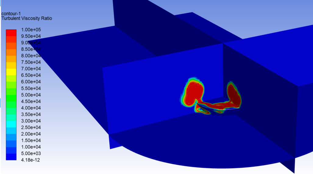
The another figure is of turbulent viscosity ratio on same plane.
I could actually increase the limiting value of viscosity ratio, but I read somewhere that the flow causing this kind of viscosity is unreal. I can be wrong. I will increase the limit and try the simulation once.
May 3, 2021 at 6:30 amDrAmine
Ansys EmployeeIncrease the value and check if it levels out or not, first. Also make sure that the level of turbulence in your domain at start is not so high. You might start with higher dissipation.
Viewing 3 reply threads- The topic ‘turbulent viscosity ratio limited to XXX cells ?’ is closed to new replies.
Innovation Space Trending discussions
 Top Contributors
-
peteroznewman
 6535
6535 -
scabo
 1906
1906 -
Dennis Chen
 1463
1463 -
javat33489
 1311
1311 -
Shyam Prasad V Atri
1022
Top Rated Tags
© 2026 Copyright ANSYS, Inc. All rights reserved.
Ansys does not support the usage of unauthorized Ansys software. Please visit www.ansys.com to obtain an official distribution.
-
Ansys Assistant will be unavailable on the Learning Forum starting January 30. An upgraded version is coming soon. We apologize for any inconvenience and appreciate your patience. Stay tuned for updates.