-
-
August 21, 2020 at 8:42 am
gartz89
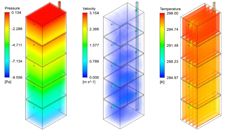
SubscriberHello, I'm reasearching the natural ventilation coupled with mechanical ventilation "FAN". The pressure difference between the external and internal pressures is the stack pressure available which can be created naturally by density differences to drive a ventilation flow through the building. Unfortunately, this stack effect in multi-storey buildings arises from the buoyancy forces which influence on the efficiency of the "small FAN" (imagine these in the bathroom). When I solve the model equations my solution gives information about the velocity distribution from the buoyancy forces, temperature distribution, pressure etc.
Everything looks good, but when I coupled some FAN as boundary conditions I would like to check what is the difference between the flow rate of every single FAN at the floors. The floors are five, the fans are 5, I add intake fan boundary conditions and add pressure jump for characteristics of the FAN. But there isn't influence from the inlet velocity if I compare with only natural ventilation.
Some boundary conditions I miss or something I have to repair in the cell zone condition I'll be glad to help me. Regards!
August 21, 2020 at 9:19 amRob
Forum ModeratorDid you use a unique boundary label for each fan?
August 21, 2020 at 9:54 amSubscriberThank you for your reply.
Yes, the boundary conditions for each fan are the same, but I don't know what did you mean about this unique boundary label. Could you give me more details? Thank you.
August 21, 2020 at 2:53 pmForum ModeratorIf each fan is the same label you can't get the individual mass flow, you'll get the sum/mean from the five surfaces. If they're the same condition but different labels you can report the results for each surface separately.
August 22, 2020 at 8:43 amSubscriberYes, but unfortunately the task is different, it is looking for the velocity inlet for each FAN. When the natural convection starts everything looks good, but in real life, these five inlets have some loss coefficient and pressure jump for each FAN. I think if have 5 more domains at the inlet and if I specified the BC for inlet vent and interface zone as a FAN (interior) and add the pressure jump there. It could give some interesting results approximately.
That's the task that I'm looking for... If you have one more idea you could say it. Thank you for your reply, Sir.
August 24, 2020 at 2:41 pmForum ModeratorIf you have 5 distinct and uniquely labelled inlets with a fixed velocity you can look at the pressure to see if there's a difference. Intake-fan allows fan curve data to be used.
August 26, 2020 at 9:04 amSubscriberDear friend I solved the problem! As I said I made 5 more domains to specified the loss coefficient of the vent. After that, I add 5 interface zone Fan boundary conditions between vent domains and the main computational domain. Finally, I specified the fan curve data as a pressure polynomial function of limits of the velocity.
So thank you for your reply. The simulation of the natural ventilation coupled with mechanical ventilation was already done. Regards!Viewing 6 reply threads- The topic ‘Natural ventilation coupled with mechanical ventilation’ is closed to new replies.
Innovation Space Trending discussions
 Top Contributors
-
peteroznewman
 5824
5824 -
scabo
 1906
1906 -
Dennis Chen
 1420
1420 -
javat33489
 1305
1305 -
Shyam Prasad V Atri
1021
Top Rated Tags
© 2026 Copyright ANSYS, Inc. All rights reserved.
Ansys does not support the usage of unauthorized Ansys software. Please visit www.ansys.com to obtain an official distribution.
-
Ansys Assistant will be unavailable on the Learning Forum starting January 30. An upgraded version is coming soon. We apologize for any inconvenience and appreciate your patience. Stay tuned for updates.