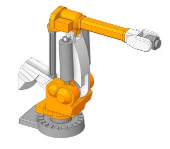
Ansys Discovery Modeling Tutorial - Robotic Arm Geometry - Lesson 8

In this lesson, you will learn how to create some complex models of a robotic arm assembly.
What is a Robotic Arm?
A robotic arm is a mechanical arm that performs operations like a human arm. It is the most commonly used robot in manufacturing industries. Robotic arms are controlled by computers and programmed to perform a variety of operations such as car painting, welding, picking and placing objects, and so on.
Modeling Approach:
Our approach to modeling will begin by analyzing the technical drawing. Download the technical drawing and other assembly components required for creating this robotic arm model here. Once we understand its characteristics, we can outline a plan for completing the robotic arm model. With a plan in place, we can begin designing the base and arm components. We will import, as well as create, several additional parts to complete the robotic arm assembly.
Check out the videos below to learn the step-by-step process for creating the robotic arm assembly using Discovery.
Part 1 - Base
Part 2 - Repair assembly
Part 3 - Robotic Arm
Recap:
This robotic arm modeling session covered several different topics. You learned how to use sketch tools such as Sweep Arc, Tangent Line, Create Corner and Trim Away. You then utilized the Pull (Draft) and Circular Pattern tools to create and modify the geometry of several components in the assembly. You cleaned problematic imported geometry using tools in the Repair tab such as Stitch and Missing Faces. Finally, you completed the robotic arm assembly using the Anchor and Align constraints.

