Connecting the Graphics using Ansys SCADE Software — Lesson 5
From the main menu we go to Insert, Graphical Panel and select Rapid Prototyper Panel…, naming and saving the graphics project in a preferred directory.
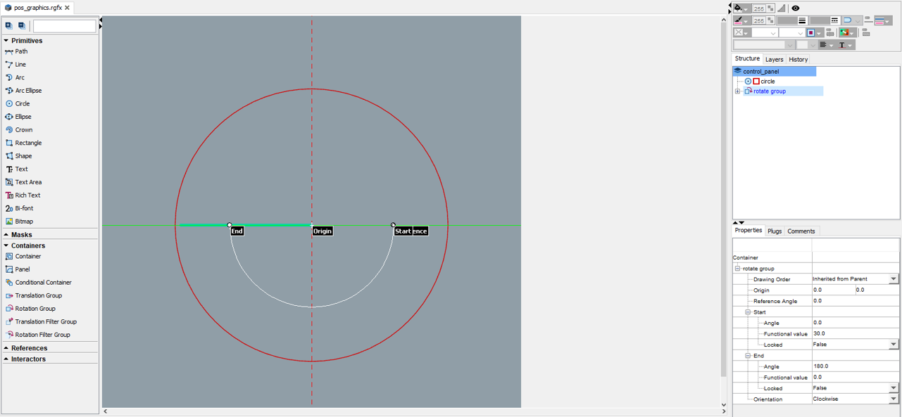
The first step is to add a New Specification, name it accordingly, and select the window size. We will then create the entities used for the graphical representation of the motor angular position: a circle, a line, and a rotational group to handle the movement. The user is free to choose the circle radius and line length, minding the window size that has already been selected. The output should look like this:

Fig 6 Motor Angular Position
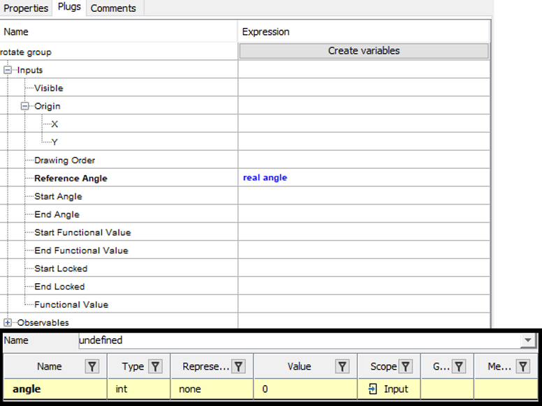
Those entities can be added through simple clicks in the UI and their exact geometric properties can be edited in the Properties tab which is by default located at the bottom right of the window as shown above. The user can also define the orientation of the rotate group as well as the reference angle. We will use this reference angle to modify the angular position of the line that is used as the indicator. To do so, we will create a variable in the Plugs tab for the reference angle and also define it in the Dictionary tab:

Fig 7 Plugs Tab
Further graphic details can be added, including text denoting the angle at each position, different coloring, or several other options available through the capabilities of Rapid Prototyper.
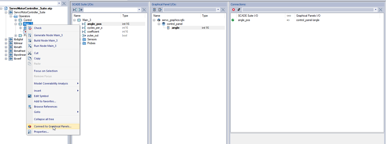
Our final step is to connect the variable we created with the Ansys SCADE software simulation. To do so we right-click on the Main operator and select Connect to Graphical Panels. Finally, in the simulation settings, under the Graphical Panels tab, we select the “Co-simulation” configuration for the Graphical Panel we have defined so we can see the outcome on both ends.

Fig 8 Connecting Graphical Panels

