
WiFi Communication and the ESP8266 Protocol
What is ESP8266?
The ESP8266 is a low-cost WiFi module that can operate as a standalone access point, a WiFi station, or both at the same time. In this project it acts as an access point and TCP server: it creates its own WiFi network, waits for a client (a phone or computer) to connect, and forwards any data that client sends to the Pico (one byte at a time) through a UART serial link.
The Pico itself has no WiFi capability. It communicates with the ESP8266 exclusively via UART: it sends text configuration commands and receives a continuous stream of bytes back. Everything that the Raspberry Pi Pico needs to know (whether the ESP8266 is ready, whether a client has connected, and what commands the client has sent) must be extracted from that single byte stream.
What is UART?
UART (Universal Asynchronous Receiver-Transmitter) is one of the simplest ways for two devices to exchange data over a serial link. It uses just two wires: one for transmitting (TX) and one for receiving (RX), with no shared clock signal between the two devices : this is what "asynchronous" means.
Because there is no clock to synchronize the two sides, both devices must agree in advance on the baud rate: the number of bits transmitted per second.
In this project, the Pico and the ESP8266 communicate at 115200 baud. If the baud rate configured on one side does not match the other, the bytes received will be garbled.
Data is sent one byte at a time, each byte framed by a start bit and a stop bit so the receiver knows exactly when a new byte begins and ends. From the Pico's point of view, sending data over UART means writing characters that get shifted out bit by bit on the TX pin, and receiving data means watching the RX pin and reconstructing bytes as they arrive, one at a time, into a small hardware buffer (FIFO) that the program then reads from.
UART is exactly the mechanism described in the rest of this section: it is the channel through which AT commands are sent, acknowledgements come back, and the +IPD frames carrying user commands arrive.
AT Commands: Configuring the ESP8266
ESP8266 is controlled through a set of short text strings called AT commands (AT for “Attention”). Each command is sent over UART as an ASCII string terminated by \r\n, and the ESP8266 replies with a text response, typically OK\r\n on success or ERROR\r\n on failure.
In this project, three AT commands are needed to bring the server up:
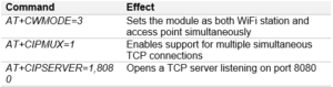
These three commands must be sent in order, and each one must be acknowledged before the next is sent. If a command fails or the ESP8266 is slow to respond, sending the next command prematurely will cause errors.
The Byte Stream: Everything Arrives as Raw Bytes
Once the server is running, the Pico receives a single continuous stream of bytes on its UART RX pin. This stream contains everything mixed: ESP8266 status messages, connection events, disconnection events, and actual user data. There are no separators between these different kinds of content, and the Pico has no way to know in advance what the next byte will be.
This is the central challenge of this architecture: the model must recognize meaningful sequences of bytes within a noisy stream, without ever being able to pause and wait for a complete message to arrive. Three specific sequences matter in this project:
- OK\r\n: bytes 79 ('O'), 75 ('K'), 13 ('\r'), 10 ('\n'): the ESP8266's acknowledgement that an AT command was accepted. The model must detect this to know when to send the next setup command.
- ,C: bytes 44 (','), 67 ('C'): a fragment of the connection notification message that the ESP8266 sends when a new TCP client connects to the server.
- +IPD,...:cmd: a framing sequence the ESP8266 wraps around every byte of incoming TCP data, detailed in the next section.
The +IPD Frame: How User Data Arrives
When a connected client sends a byte of data, the ESP8266 does not forward it directly. It wraps it in a notification frame with the following format:
+IPD,<connection_id>,<length>:<data>
For example, if the user sends the character L for the command to send, the Pico receives:
+IPD,0,1:L
The actual command (here, the single character L) is the very last byte, after the +, the I, the P, the D, the connection id digit, the comma, the length digit and the colon. The Scade One model must walk through all these bytes one by one before it reaches the payload. If any unexpected byte appears along the way, the parser must reset to the beginning and wait for the next +.
This is why parsing the stream requires a state machine with many intermediate states rather than a simple character comparison: the model never sees the full frame at once, only one byte per cycle.
Summary: What the Scade One Model Must Do
Given these constraints, the Scade One model has four distinct responsibilities running in parallel every cycle:
- Detect OK\r\n to advance the setup sequence
- Detect a new client connection
- Parse +IPD frames to extract the command byte
- Sequence the three AT commands at startup
For the Servo: This project reuses the Servo operator built in the Servo tutorial, rather than rebuilding it from scratch. To do this, open the Servo project in Scade One, then in the Workspace view, link the current WIFI project to the Servo project.
Next, inside the WIFI module, click the '+' button and select Create use directive, then write use Servo. This makes the Servo operator from the other project visible inside the WIFI module, without copying any code.
Inside the CarController operator, you can now simply select the Servo operator from the panel and drag it into the CarController diagram. Connect its input (degrees) and its output (duty) to the corresponding wires in CarController. There is no need to copy-paste the operator itself: the use directive keeps it linked to the original Servo project, so any future fix made there will apply here as well.