
Designing the Model in Scade One
Tick Rate and Execution Semantics
Scade One uses synchronous semantics: the model is called at every clock tick.
In this project, the clock period is set to 10 ms, which corresponds to a clock frequency of 100 Hz. This is significantly higher than the state-change frequency (triggered by the user) and ensures reliable edge detection.
Inputs/Outputs of Model
Input:

Output:

Local variable:

Operators and state machines
FED Operator: Falling Edge Detection
Detects when the button is released (transition from 1 to 0). It’s the same operator as for the blinking LED project (see first tutorial).
State Machine
Three main states control the buzzer frequency. The transition between states is triggered by buttonL (the falling edge of the button):
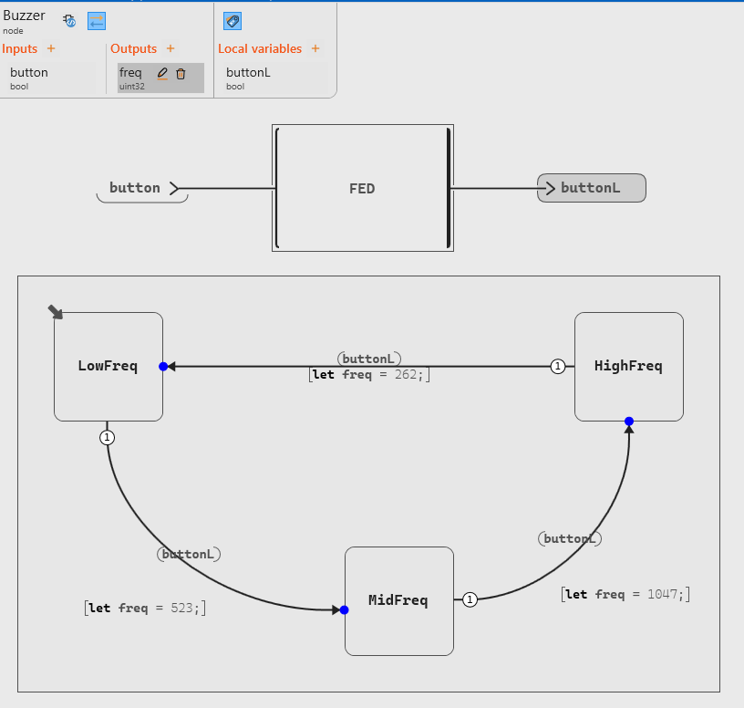
Buzzer
As in the first tutorial blinking LED, we assign the next frequency value inside the state you are leaving, not inside the state it belongs to. For example, the value 523 Hz is assigned to freq in the LowFreq transition to MidFreq, not in the MidFreq state directly.
Debug and Early Validation
The built-in debug of Scade One is a very useful and visual tool to observe how the system works, using cycles (not seconds). When lauching it, we can change the value of the button (boolean: true or false) to observe that the system works as expected, as the changement of states within the automatons. Also, with the debug we can verify that buttonL becomes true exactly one cycle after the button is released.
This functionality of Scade One must be used to avoid incorrect behavior or errors when uploading the code in the Raspberry Pi Pico.
When debugging, we can see that we start from LowFreq with freq = 262, and when we change the button state to true (press step) then false, we change from LowFreq to MidFreq with freq = 523, and so on for the next states.
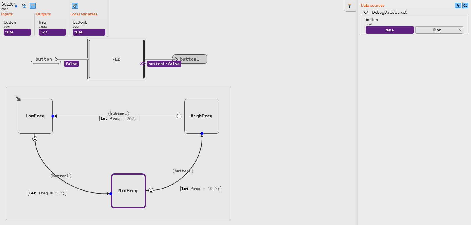
Debug buzzer