Geometry — Lesson 3
For this problem, we are going to import the geometry, which was designed using CAD software, into Ansys Workbench.
Click here to download the geometry file.
Save the file somewhere convenient, like your desktop or your working directory.
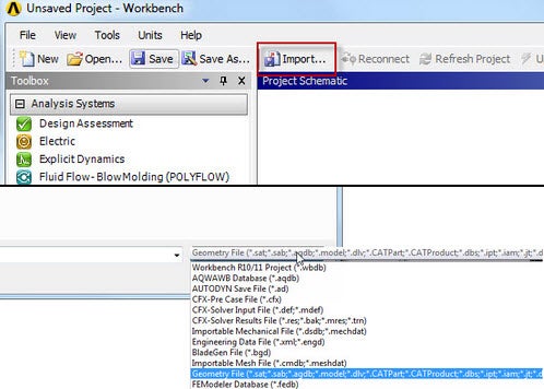
Use the import button in the Workbench to open the file. (Remember to select "Geometry File" from the drop down menu, so you can see .STEP files.)
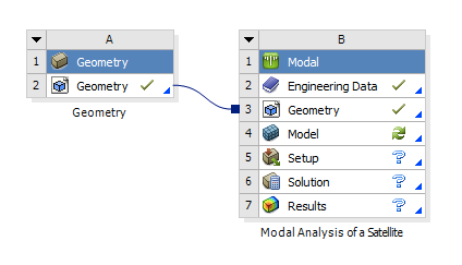
Once we are satisfied with our geometry, we can close the DesignModeler. Now, we should be looking at the Project window. To connect the geometry to the project, click and drag. As soon as you drag the box, the Ansys software will highlight the geometry and model boxes in the main project.
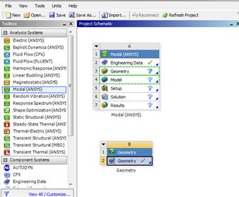
Drag and drop the geometry box onto ![]()
We can now survey the imported geometry by double clicking ![]()
Internal Components
The internal components of this satellite have been simplified to reduce modal analysis run time. While this CubeSat structure is simple, larger satellites often have a more complex interior with a wide array of components and structural stiffeners. Features such as small extrusions, fillets not in contact with the frame, and holes may be omitted to reduce the computational load of the simulation.
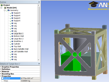
In order to simulate the mass of the internal components, we must apply a specific density to each component based on its corresponding volume. The volume of each component can be found by clicking on the desired part under Geometry in the Design Modeler and opening the Properties tab in the details window.
In the image below, you can see the volume for "Large Box 1."
Before applying a specific density to this component, we must create a new material with a given density. This is done through Engineering Data on the Ansys Workbench. It is important to note that we will only be changing the density of the material, as other material properties have little to no effect on the resonant frequency of the satellite. We will simply duplicate the Al 6061-T6 and change the density. Right click on Al 6061-T6 >Duplicate. Duplicate three times, then rename the new materials Large Box, Small Box, and Cylinder.
For the purposes of this tutorial, the densities for the components are provided (make sure the correct unit kg/m^3 is selected):
Large Box Density = 1000 kg/m^3
Small Box Density = 900 kg/m^3
Cylinder Density = 1200 kg/m^3
1. Assigning Material to a Component
Now we can assign the new material densities to the internal components. Left click Return to Project > Model to return to the DesignModeler. Now open up the Geometry drop-down list and select "Large Box 1" and "Large Box 2." Right click Material > Assignment > Large Box.
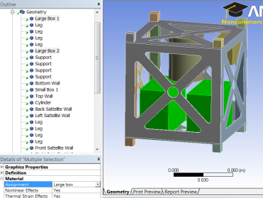
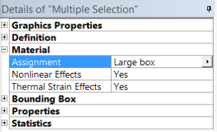
Now assign the small box material to "Small Box 1" and the cylinder material to "Cylinder." The internal components will now simulate a more realistic mass rather than a solid piece of aluminum.
2. Geometry Connections
To simplify the model, we assume that most of the structure is rigid and bonded together. However, for our model we will assume that none of the satellite walls are bonded to each othe; instead they are bolted to the four supports. Modeling these connections can be achieved in a few steps.
First, right click Connections > Create Automatic Connections. This creates a bonded connection between all parts that touch each other.
Now maximize the Connections tab, right click Contacts > Rename Based on Definition. You can now see the connection type and the names of the parts that are bonded to each other.
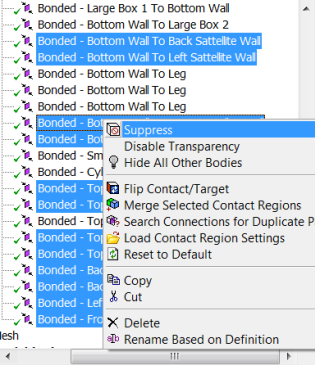
Because the walls are not physically bonded to each other, we must suppress every wall-to-wall connection. While holding the Ctrl key, select every wall-to-wall connection. There should be 12 wall-to-wall connections. Right click the selection > Supress.
If you are using Ansys 15.0, please go through the following topic for the procedure for turning on the Auto Constraints feature before creating sketches in Ansys DesignModeler.

